
Related Manuals for Canvas Abbotsford 064-4015-0


Summary of Contents for Canvas Abbotsford 064-4015-0
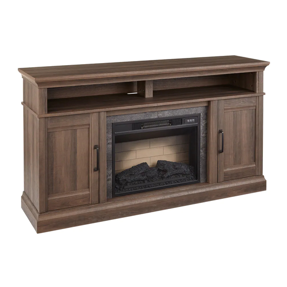
- Page 1 60” ABBOTSFORD MEDIA FIREPLACE MODEL NO. 064-4015-0 FAUX STONE SURROUND WOOD SURROUND ASSEMBLY INSTRUCTIONS HAVING TROUBLE? TOLL-FREE: 1-888-670-6684...
- Page 2 From on-trend furniture pieces to holiday décor and all your outdoor living essentials, CANVAS®️ makes it easy to refresh your space to reflect your unique style and the way you live every day. We would love to hear from you and welcome your thoughtful feedback.
- Page 3 TABLE OF CONTENTS Safety Information Parts List Step-by-step Guide Operating Instructions Cleaning and Maintenance Troubleshooting Warranty Information WARNING! TO REDUCE THE RISK OF SERIOUS INJURY, READ THE FOLLOWING SAFETY INSTRUCTIONS BEFORE ASSEMBLING AND OPERATING THIS FIREPLACE. When using electrical appliances, basic precautions should always be followed to reduce the risk of fire, electric shock and injury to persons, including the following: •...
- Page 4 TOOLS REQUIRED Cross-head Pliers 2 people Screwdriver SAFETY INFORMATION IMPORTANT SAFETY INFORMATION Use this appliance only as described in the manual. Any other use is not recommended by the manufacturer and may cause fire, electric shock or injury to persons. Read all instructions before installing or using the fireplace.
- Page 5 overheats or abnormal heating occurs, 14. Under no circumstances should this the thermostat protective device cuts fireplace be modified. Parts having off the power supply to avoid fireplace to be removed for servicing must damage and reduce the risk of fire. be replaced prior to operating this fireplace again.
- Page 6 PARTS LIST ITEM DESCRIPTION QUANTITY Top Panel Lower Left Side Panel Lower Right Side Panel Middle Shelf Bottom Panel Bottom Front Stretcher Bottom Rear Stretcher Lower Left Partition Panel Lower Right Partition Panel Faux Stone Middle Crossbar Faux Stone Left Middle Stile Faux Stone Right Middle Stile Lower Partition Moulding Upper Side Panel...
- Page 7 OPTIONAL WOOD SURROUND PARTS ABBOTSFORD MEDIA FIREPLACE...
- Page 8 PARTS LIST ITEM DESCRIPTION QUANTITY Wood Dowel 49 + (5) Cam Lock 52 + (6) Cam Bolt 52 + (6) Short Flat-head Screw 4 + (1) Medium Flat-head Screw 4 + (1) Long Flat-head Screw 4 + (1) Door Stopper Washer-head Screw 42+ (5) Metal Bracket...
- Page 9 ABBOTSFORD MEDIA FIREPLACE...
- Page 10 STEP-BY-STEP GUIDE READ CAREFULLY BEFORE STARTING ASSEMBLY This fireplace has two options for assembly. It can be assembled with FAUX STONE WOOD to frame the insert. If assembling with the FAUX STONE SURROUND, use parts J, K and L. If assembling with the WOOD SURROUND, use parts J1, K1 and L1. Choose one option before you begin assembly, and discard the parts you do not need.
- Page 11 STEP 1 REQUIRES A, B, C, CC Securely screw the CAM BOLTS (CC) into the designated small holes on the TOP PANEL (A) and LOWER SIDE PANELS (B and C) using a cross-head screwdriver. X 12 Not actual size ABBOTSFORD MEDIA FIREPLACE...
- Page 12 STEP-BY-STEP GUIDE STEP 2 REQUIRES D, E, O, Q, CC Securely screw the CAM BOLTS (CC) into the designated small holes on the MIDDLE SHELF (D), BOTTOM PANEL (E), UPPER SIDE PANEL MOULDINGS (O) and UPPER PARTITION PANEL MOULDING (Q) using a cross-head screwdriver. X 24 Not actual size ABBOTSFORD MEDIA FIREPLACE...
- Page 13 STEP 3 REQUIRES E, B, C, AA, TT Glue the WOOD DOWELS (AA) into the inner holes on the BOTTOM PANEL (E) and LOWER SIDE PANELS (B and C) as shown. Not actual size ABBOTSFORD MEDIA FIREPLACE...
- Page 14 STEP-BY-STEP GUIDE STEP 4 FAUX STONE OPTION REQUIRES F, G, J, AA, TT WOOD OPTION REQUIRES F, G, J1, AA, TT Glue the WOOD DOWELS (AA) into the inner holes on the BOTTOM FRONT STRETCHER (F), BOTTOM REAR STRETCHER (G), FAUX STONE MIDDLE CROSSBAR (J) WOOD MIDDLE CROSSBAR (J1) as shown.
- Page 15 STEP 5 FAUX STONE OPTION REQUIRES D, J, BB WOOD OPTION REQUIRES D, J1, BB Attach the FAUX STONE MIDDLE CROSSBAR (J) WOOD MIDDLE CROSSBAR (J1) to the MIDDLE SHELF (D) by engaging three CAM LOCKS (BB). Not actual size FAUX STONE OPTION SHOWN HERE ABBOTSFORD MEDIA FIREPLACE...
- Page 16 STEP-BY-STEP GUIDE STEP 6 REQUIRES D, EE, GG Fasten two DOOR STOPPERS (GG) to the MIDDLE SHELF (D) with two MEDIUM FLAT-HEAD SCREWS (EE) per stopper. Not actual size ABBOTSFORD MEDIA FIREPLACE...
- Page 17 STEP 7 REQUIRES E, G, BB Attach the BOTTOM REAR STRETCHER (G) to the BOTTOM PANEL (E) by engaging three CAM LOCKS (BB). Not actual size ABBOTSFORD MEDIA FIREPLACE...
- Page 18 STEP-BY-STEP GUIDE STEP 8 REQUIRES E, F, BB Attach the BOTTOM FRONT STRETCHER (F) to the BOTTOM PANEL (E) by engaging four CAM LOCKS (BB). Not actual size ABBOTSFORD MEDIA FIREPLACE...
- Page 19 STEP 9 REQUIRES B, C, E, F, G, BB Align the large holes on both LOWER SIDE PANELS (B and C) with inserted WOOD DOWELS (AA) and press them together. Attach the LOWER SIDE PANELS (B and C) in place by engaging six CAM LOCKS (BB). Not actual size ABBOTSFORD MEDIA FIREPLACE...
- Page 20 STEP-BY-STEP GUIDE STEP 10 REQUIRES H, I, M, CC Securely screw the CAM BOLTS (CC) into the designated holes on the LOWER PARTITION PANELS (H and I) and LOWER PARTITION MOULDINGS (M) using a cross-head screwdriver. X 10 Not actual size ABBOTSFORD MEDIA FIREPLACE...
- Page 21 STEP 11 FAUX STONE OPTION REQUIRES H, I, K, L, AA, TT WOOD OPTION REQUIRES H, I, K1, L1, AA, TT Glue the WOOD DOWELS (AA) into the inner holes on the LOWER PARTITION PANELS (H and I), FAUX STONE MIDDLE STILES (K and L) WOOD MIDDLE STILES (K1 and L1) as shown.
- Page 22 STEP-BY-STEP GUIDE STEP 12 FAUX STONE OPTION REQUIRES H, I, K, L, BB WOOD OPTION REQUIRES H, I, K1, L1, BB Attach the FAUX STONE MIDDLE STILES (K and L) WOOD MIDDLE STILES (K1 and L1) to the LOWER PARTITION PANELS (H and I) by engaging three CAM LOCKS (BB) per stile.
- Page 23 STEP 13 REQUIRES H, I, M, BB Attach the LOWER PARTITION MOULDINGS (M) to the opposite side of LOWER PARTITION PANELS (H and I) by engaging two CAM LOCKS (BB) per moulding. Not actual size The outer edges are flush ABBOTSFORD MEDIA FIREPLACE...
- Page 24 STEP-BY-STEP GUIDE STEP 14 REQUIRES E, H, I, FF Attach the LOWER PARTITION PANELS (H and I) to the BOTTOM PANEL (E) with four LONG FLAT-HEAD SCREWS (FF). Not actual size ABBOTSFORD MEDIA FIREPLACE...
- Page 25 STEP 15 REQUIRES D, BB Ask for assistance to position the MIDDLE SHELF (D) onto the inserted WOOD DOWELS (AA) on the vertical panels properly, and fasten it in place by engaging eight CAM LOCKS (BB). Not actual size ABBOTSFORD MEDIA FIREPLACE...
- Page 26 STEP-BY-STEP GUIDE STEP 16 REQUIRES F, B, C JJ, LL Using the pilot holes as a guide, fasten two TRIANGLE METAL PLATES (JJ) at the bottom joints between the BOTTOM FRONT STRETCHER (F) and LOWER SIDE PANELS (B and C) using four LONG PAN-HEAD SCREWS (LL) per plate. Not actual size ABBOTSFORD MEDIA FIREPLACE...
- Page 27 STEP 17 REQUIRES KK Screw the FLOOR LEVELLERS (KK) into the threaded sockets on the TRIANGLE METAL PLATES (JJ) and set to the correct height. Not actual size ABBOTSFORD MEDIA FIREPLACE...
- Page 28 STEP-BY-STEP GUIDE STEP 18 REQUIRES D, CC Stand the assembled unit upright. Securely screw the CAM BOLTS (CC) into the designated small holes on the top face of MIDDLE SHELF (D) using a cross-head screwdriver. Not actual size ABBOTSFORD MEDIA FIREPLACE...
- Page 29 STEP 19 REQUIRES N, O, P, AA, TT Glue the WOOD DOWELS (AA) into the inner holes on the UPPER SIDE PANELS (N), UPPER SIDE PANEL MOULDINGS (O) and UPPER PARTITION PANEL (P) as shown. X 17 Not actual size ABBOTSFORD MEDIA FIREPLACE...
- Page 30 STEP-BY-STEP GUIDE STEP 20 REQUIRES N, O, P, Q, BB Attach the UPPER SIDE PANEL MOULDINGS (O) to UPPER SIDE PANELS (N) by engaging two CAM LOCKS (BB) in each. Repeat the same step to attach the UPPER PARTITION PANEL MOULDING (Q) to the UPPER PARTITION PANEL (P).
- Page 31 STEP 21 REQUIRES D, N, P, BB Attach the UPPER SIDE PANELS (N) and UPPER PARTITION PANEL (P) to the MIDDLE SHELF (D) by engaging six CAM LOCKS (BB). Not actual size ABBOTSFORD MEDIA FIREPLACE...
- Page 32 STEP-BY-STEP GUIDE STEP 22 REQUIRES A, BB Place the TOP PANEL (A) onto the inserted WOOD DOWELS (AA) on the vertical panels properly, and fasten it in place with six CAM LOCKS (BB). Not actual size ABBOTSFORD MEDIA FIREPLACE...
- Page 33 STEP 23 REQUIRES J, K, L, DD, II Ask for assistance to lay down the unit on its front edge as shown. Attach two METAL BRACKETS (II) at the joints where the MIDDLE CROSSBAR (J or J1) meets the MIDDLE STILES (K and L, or K1 and L1) with four SHORT FLAT-HEAD SCREWS (DD).
- Page 34 STEP-BY-STEP GUIDE STEP 24 REQUIRES S, T, HH Pick up the UPPER BACK PANEL (S) and align the pre-drilled holes against the upper long edge with the pilot holes on the back stretcher of the TOP PANEL (A). Attach it in place using the provided WASHER-HEAD SCREWS (HH).
- Page 35 STEP 25 REQUIRES U, NN, OO, PP, QQ Extend two HINGES (OO) and rest the hinge cups onto the cutouts of one DOOR PANEL (U). Secure the door hinges in place with two ZINC SCREWS (NN) in each. Attach one HANDLE (PP) to the front side of the door with two HANDLE BOLTS (QQ). Repeat to attach the other HANDLE (PP) and HINGES (OO) to the other DOOR PANEL (U).
- Page 36 STEP-BY-STEP GUIDE STEP 26 REQUIRES B, C, U, OO, NN Stand the unit upright and position it near the final location. Pick up the DOOR PANELS (U) and fasten the HINGE BASES onto the LOWER SIDE PANELS (B and C) with four ZINC SCREWS (NN) per hinge base. X 16 Not actual size ABBOTSFORD MEDIA FIREPLACE...
- Page 37 STEP 27 REQUIRES U, R, MM Open the DOORS (U) and insert four SHELF SUPPORTS (MM) in the holes at the desired height inside each side compartment. Make sure you place the four shelf supports at the same level so the shelf is not tilted. Tilt and rest the ADJUSTABLE SHELVES (R) onto the shelf supports.
- Page 38 STEP-BY-STEP GUIDE STEP 28 REQUIRES RR Plug the CAM LOCK COVERS (RR) onto the visible cam locks to conceal the cams. X 32 Not actual size ABBOTSFORD MEDIA FIREPLACE...
- Page 39 STEP 29 Unpack the FIREPLACE INSERT (W) from the inner box and fasten the TOP TRIM (X) to the top of the fireplace insert using two of the SHORT PAN-HEAD SCREWS (ZZ) included with the insert. Make sure that the right angle side points towards the front of the unit.
- Page 40 STEP-BY-STEP GUIDE STEP 30 Lift the FIREPLACE INSERT (W) carefully into the back of the assembled mantel and centre it in the opening. DO NOT drag the insert across the BOTTOM PANEL (E) as it may scratch the unit. Fasten the FIREPLACE INSERT (W) to the mantel with six SHORT PAN-HEAD SCREWS (ZZ) as shown.
- Page 41 STEP 31 REQUIRES A, SS Remove the paper backing on the ACRYLIC STOPPER (SS), then properly align the acrylic stopper into the cutout on the acrylic stopper template on the front of the TOP PANEL (A). Press down on the acrylic stopper to help adhesion. At the back of TOP PANEL (A), grip the heads of plastic tacks with pliers, and with a twisting motion, pull tacks loose to remove the acrylic stopper template.
- Page 42 STEP-BY-STEP GUIDE STEP 32 REQUIRES VV With assistance, position the assembled fireplace at the desired location against a wall. If necessary, adjust the installed FLOOR LEVELLERS (KK) by hand to correct tilting and level the doors, until the unit is level. Follow the instructions printed on the plastic bag containing the tipping restraint hardware to attach the TIPPING RESTRAINT HARDWARE (VV) to the unit and the wall.
- Page 43 STEP 32 Put the unit in place. Maximum load 80 lb (36.3 kg) Place TV behind the stopper Maximum load 50 lb (22.7 kg) WARNING! For use with televisions weighing 80 lb (36.3 kg) or less. Use with heavier televisions may cause instability and/or tip over resulting in death or serious injury.
- Page 44 OPERATING INSTRUCTIONS IDENTIFYING THE CONTROL PANEL The control panel is located on the top right corner of the fireplace/heater unit. The control panel contains the main power (1), flame control (2) and heater control (3). 1 2 3 USING THE MAIN POWER BUTTON Press the power button (1) to turn the fireplace/heater unit on and off.
- Page 45 USING THE DEMO MODE For use in retail store. To turn Demo Mode on, press and hold the power button (1) for 10 seconds. The log lights flash several times to indicate that the Demo Mode is turned on. Demo Mode deactivates the heater and all front control panel buttons except the flame control button.
- Page 46 OPERATING INSTRUCTIONS USING THE FLAME CONTROL Press the flame button (2) to set the flames for different levels of flame brightness. Control the flame brightness as shown: Button Press Flame Level Fireplace Appearance 1st press Medium Flames Medium, Logs Glow Medium 2nd press Flames Low, Logs Glow Low 3rd press...
- Page 47 REPLACING THE REMOTE CONTROL BATTERY The battery is supplied with the remote control. Before first use, remove the plastic sheet insulating the battery. For replacement battery, use a lithium-based CR2025 battery. Please follow the sequence below to replace the battery. 1.
- Page 48 OPERATING INSTRUCTIONS BATTERY SAFETY WARNINGS WARNING: Do not ingest batteries. • Non-rechargeable batteries are not to be recharged. • Batteries are to be inserted with the correct polarity. • Exhausted batteries are to be removed from the product. • Always purchase the correct size and grade of battery most suitable for the intended use.
- Page 49 CLEANING AND MAINTENANCE DISPOSAL OF USED BATTERY A battery may contain hazardous substances that could be dangerous to the environment and human health. This symbol marked on the battery and/or packaging indicates that the used battery shall not be treated as municipal waste. Instead it should be left at an appropriate collection point for recycling.
- Page 50 TROUBLESHOOTING PROBLEM SOLUTION Using the fireplace with the heater • Fireplace is not to be used with a power strip or ON causes a trip in my power extension cord. Make sure your unit is plugged by itself circuit. into a standard qualifying wall outlet that is properly grounded.
- Page 51 WARRANTY INFORMATION This CANVAS product carries a one (1) year warranty against defects in workmanship and materials. Trileaf Distribution agrees to replace the defective product free of charge within the stated warranty period, when returned by the original purchaser with proof of purchase. This product is not guaranteed against wear or breakage due to misuse and/or abuse.
- Page 52 Exclusively at Canadian Tire...
- Page 53 FOYER MULTIMÉDIA ABBOTSFORD DE 60 PO DE MODÈLE : 064-4015-0 ENCADREMENT EN FAUSSE PIERRE ENCADREMENT EN BOIS INSTRUCTIONS D’ASSEMBLAGE VOUS RENCONTREZ DES PROBLÈMES? NUMÉRO SANS FRAIS: 1 888 670-6684...
- Page 54 INSPIRÉ PAR LE CANADA Nous croyons au pouvoir de la décoration pour donner son âme à votre maison. C’est pour cela que les collections CANVAS s’inspirent des Canadiens et de leur style de vie. Qu’il s’agisse de meubles tendance, de décorations pour les fêtes ou pour le plein...
- Page 55 TABLE DES MATIÈRES Consignes de sécurité Liste des pièces Guide étape par étape Instructions d’utilisation Nettoyage et entretien Dépannage Renseignements sur la garantie AVERTISSEMENT! POUR RÉDUIRE LE RISQUE DE BLESSURES GRAVES, LISEZ LES INSTRUCTIONS DE SÉCURITÉ SUIVANTES AVANT D’ASSEMBLER ET D’UTILISER CE FOYER. Lors de l’utilisation d’appareils électriques, des précautions de base doivent être respectées afin de réduire le risque d’incendie, de choc électrique et de blessures, y compris ce qui suit :...
- Page 56 OUTILS REQUIS Tournevis à Pince 2 personnes tête cruciforme CONSIGNES DE SÉCURITÉ CONSIGNES DE SÉCURITÉ IMPORTANTES Utilisez cet appareil uniquement comme décrit dans ce guide d’utilisation. Toute autre utilisation non recommandée par le fabricant peut provoquer un incendie, une décharge électrique ou des blessures corporelles.
- Page 57 le dispositif de protection du thermostat 13. Toute réparation de ce foyer doit être coupe l’alimentation électrique pour effectuée par un technicien qualifié. éviter d’endommager le foyer et réduire 14. Ce foyer ne doit en aucun cas être les risques d’incendie. modifié.
- Page 58 LISTE DES PIÈCES ARTICLE DESCRIPTION QUANTITÉ Panneau supérieur Panneau latéral inférieur gauche Panneau latéral inférieur droit Tablette intermédiaire Panneau inférieur Entretoise avant inférieure Entretoise arrière inférieure Panneau de séparation inférieur gauche Panneau de séparation inférieur droit Barre transversale moyenne en fausse pierre Montant intermédiaire gauche en fausse pierre Montant intermédiaire droit en fausse pierre Moulure de séparation inférieure...
- Page 59 PIÈCES D’ENCADREMENT EN BOIS FACULTATIVES FOYER MULTIMÉDIA ABBOTSFORD...
- Page 60 LISTE DES PIÈCES ARTICLE DESCRIPTION QUANTITÉ Goujon de bois 49 + (5) Came de verrouillage 52 + (6) Boulon à came 52 + (6) Petite vis à tête plate 4 + (1) Vis moyenne à tête plate 4 + (1) Longue vis à...
- Page 61 FOYER MULTIMÉDIA ABBOTSFORD...
- Page 62 GUIDE ÉTAPE PAR ÉTAPE LIRE ATTENTIVEMENT AVANT DE COMMENCER L’ASSEMBLAGE Ce foyer a deux options d’assemblage. Il peut être assemblé avec de la FAUSSE PIERRE du BOIS pour encadrer le foyer. Si vous assemblez le foyer avec l’ENCADREMENT EN FAUSSE PIERRE, utilisez les pièces J, K et L.
- Page 63 ÉTAPE 1 PIÈCES REQUISES : A, B, C, CC Vissez fermement les BOULONS DE CAME (CC) dans les petits trous désignés sur le PANNEAU SUPÉRIEUR (A) et les PANNEAUX LATÉRAUX INFÉRIEURS (B et C) à l’aide d’un tournevis à tête cruciformer. X 12 Non illustré...
- Page 64 GUIDE ÉTAPE PAR ÉTAPE ÉTAPE 2 PIÈCES REQUISES : D, E, O, Q, CC Vissez fermement les BOULONS DE CAME (CC) dans les petits trous désignés sur la TABLETTE INTERMÉDIAIRE (D), le PANNEAU INFÉRIEUR (E), les MOULURES DE PANNEAU LATÉRAL SUPÉRIEUR (O) et la MOULURE DE PANNEAU DE SÉPARATION SUPÉRIEUR (Q) à...
- Page 65 ÉTAPE 3 PIÈCES REQUISES : E, B, C, AA, TT Collez les GOUJONS DE BOIS (AA) dans les trous intérieurs du PANNEAU INFÉRIEUR (E) et des PANNEAUX LATÉRAUX INFÉRIEURS (B et C) comme indiqué. Non illustré à taille réelle FOYER MULTIMÉDIA ABBOTSFORD...
- Page 66 GUIDE ÉTAPE PAR ÉTAPE ÉTAPE 4 OPTION DE FAUSSE PIERRE NÉCESSITE F, G, J, AA, TT OPTION DE BOIS NÉCESSITE F, G, J1, AA, TT Collez les GOUJONS DE BOIS (AA) dans les trous intérieurs de l’ENTRETOISE AVANT INFÉRIEURE (F), de l’ENTRETOISE ARRIÈRE INFÉRIEURE (G), de la BARRE TRANSVERSALE INTERMÉDIAIRE EN FAUSSE PIERRE (J) de la BARRE TRANSVERSALE INTERMÉDIAIRE EN BOIS (J1), comme illustré.
- Page 67 ÉTAPE 5 OPTION DE FAUSSE PIERRE NÉCESSITE D, J, BB OPTION DE BOIS NÉCESSITE D, J1, BB Fixez la BARRE TRANSVERSALE INTERMÉDIAIRE EN FAUSSE PIERRE (J) la BARRE INTERMÉDIAIRE EN BOIS (J1) à la TABLETTE INTERMÉDIAIRE (D) en engageant trois CAMES DE VERROUILLAGE (BB). Non illustré...
- Page 68 GUIDE ÉTAPE PAR ÉTAPE ÉTAPE 6 PIÈCES REQUISES : D, EE, GG Fixez deux BUTÉES DE PORTE (GG) à la TABLETTE INTERMÉDIARE (D) au moyen de deux VIS MOYENNES À TÊTE PLATE (EE) par butée. Non illustré à taille réelle FOYER MULTIMÉDIA ABBOTSFORD...
- Page 69 ÉTAPE 7 PIÈCES REQUISES : E, G, BB Fixez L’ENTRETOISE ARRIÈRE INFÉRIEURE (G) au PANNEAU INFÉRIEUR (E) en engageant trois CAMES DE VERROUILLAGE (BB). Non illustré à taille réelle FOYER MULTIMÉDIA ABBOTSFORD...
- Page 70 GUIDE ÉTAPE PAR ÉTAPE ÉTAPE 8 PIÈCES REQUISES : E, F, BB Fixez L’ENTRETOISE AVANT INFÉRIEURE (G) au PANNEAU INFÉRIEUR (E) en engageant quatre CAMES DE VERROUILLAGE (BB). Non illustré à taille réelle FOYER MULTIMÉDIA ABBOTSFORD...
- Page 71 STEP 9 PIÈCES REQUISES : B, C, E, F, G, BB Alignez les gros trous des deux PANNEAUX LATÉRAUX INFÉRIEURS (B et C) avec les GOUJONS DE BOIS (AA) insérés et appuyez-les ensemble. Fixez les PANNEAUX LATÉRAUX INFÉRIEURS (B et C) en place en engageant six CAMES DE VERROUILLAGE (BB).
- Page 72 GUIDE ÉTAPE PAR ÉTAPE ÉTAPE 10 PIÈCES REQUISES : H, I, M, CC Vissez solidement les BOULONS DE CAME (CC) dans les trous désignés sur les PANNEAUX DE SÉPARATION INFÉRIEURS (H et I) et les MOULURES DE SÉPARATION INFÉRIEURES (M) à l’aide d’un tournevis à tête cruciforme. X 10 Non illustré...
- Page 73 ÉTAPE 11 OPTION DE FAUSSE PIERRE NÉCESSITE H, I, K, L, AA, TT OPTION DE BOIS NÉCESSITE H, I, K1, L1, AA, TT Collez les GOUJONS DE BOIS (AA) dans les trous intérieurs des PANNEAUX DE SÉPARATION INFÉRIEURS (H et I), des MONTANTS INTERMÉDIAIRES EN FAUSSE PIERRE (K et L) des MONTANTS INTERMÉDIAIRES EN BOIS (K1 et L1) comme indiqué.
- Page 74 GUIDE ÉTAPE PAR ÉTAPE ÉTAPE 12 OPTION DE FAUSSE PIERRE NÉCESSITE H, I, K, L, BB OPTION DE BOIS NÉCESSITE H, I, K1, L1, BB Fixez les MONTANTS INTERMÉDIAIRES EN FAUSSE PIERRE (K et L) les MONTANTS INTERMÉDIAIRES EN BOIS (K1 et L1) aux PANNEAUX DE SÉPARATION INFÉRIEURS (H et I) en engageant trois CAMES DE VERROUILLAGE (BB) par montant.
- Page 75 ÉTAPE 13 PIÈCES REQUISES : H, I, M, BB Fixez les MOULURES DE SÉPARATION INFÉRIEURES (M) sur le côté opposé des PANNEAUX DE SÉPARATION INFÉRIEURS (H et I) en engageant deux CAMES DE VERROUILLAGE (BB) par moulure. Non illustré à taille réelle Les bords extérieurs affleurent FOYER MULTIMÉDIA ABBOTSFORD...
- Page 76 GUIDE ÉTAPE PAR ÉTAPE ÉTAPE 14 PIÈCES REQUISES : E, H, I, FF Fixez LES PANNEAUX DE SÉPARATION (H ET I) au PANNEAU INFÉRIEUR (E) au moyen de quatre LONGUES VIS À TÊTE PLATE (FF). Non illustré à taille réelle FOYER MULTIMÉDIA ABBOTSFORD...
- Page 77 ÉTAPE 15 PIÈCES REQUISES : D, BB Demandez de l’aide pour positionner correctement le PANNEAU INTERMÉDIAIRE (D) sur les GOUJONS DE BOIS (AA) insérés sur les panneaux verticaux, et fixez-le en place en engageant huit CAMES DE SERRURE (BB). Non illustré à taille réelle FOYER MULTIMÉDIA ABBOTSFORD...
- Page 78 GUIDE ÉTAPE PAR ÉTAPE ÉTAPE 16 PIÈCES REQUISES : F, B, C JJ, LL En utilisant les avant-trous comme guide, fixez deux PLAQUES DE MÉTAL TRIANGULAIRE (JJ) au niveau des joints inférieurs entre l’ENTRETOISE AVANT INFÉRIEURE (F) et les PANNEAUX LATÉRAUX INFÉRIEURS (B et C) au moyen de quatre LONGUE VIS À TÊTE CYLINDRIQUE BOMBÉE (LL) par plaque.
- Page 79 ÉTAPE 17 PIÈCE REQUISE : KK Vissez les PIEDS DE NIVELLEMENT (KK) dans les douilles filetées des PLAQUES EN MÉTAL TRIANGULAIRES (JJ) et réglez à la bonne hauteur. Non illustré à taille réelle FOYER MULTIMÉDIA ABBOTSFORD...
- Page 80 GUIDE ÉTAPE PAR ÉTAPE ÉTAPE 18 PIÈCES REQUISES : D, CC Redressez l’appareil. Vissez fermement les BOULONS DE CAME (CC) dans les petits trous désignés sur la face supérieure de la TABLETTE INTERMÉDIAIRE (D) à l’aide d’un tournevis à tête cruciforme.
- Page 81 ÉTAPE 19 PIÈCES REQUISES : N, O, P, AA, TT Collez les GOUJONS DE BOIS (AA) dans les trous intérieurs des PANNEAUX LATÉRAUX SUPÉRIEURS (N), des MOULURES DU PANNEAU LATÉRAL SUPÉRIEUR (O) et du PANNEAU DE SÉPARATION SUPÉRIEUR (P) comme illustré. X 17 Non illustré...
- Page 82 GUIDE ÉTAPE PAR ÉTAPE ÉTAPE 20 PIÈCES REQUISES : N, O, P, Q, BB Fixez LES MOULURES DU PANNEAU LATÉRAL SUPÉRIEUR (O) aux PANNEAUX LATÉRAUX SUPÉRIEURS (N) en engageant chacun deux CAMES DE VERROUILLAGE (BB). Répétez la même étape pour fixer la MOULURE DU PANNEAU DE SÉPARATION SUPÉRIEUR (Q) au PANNEAU DE SÉPARATION SUPÉRIEUR (P).
- Page 83 ÉTAPE 21 PIÈCES REQUISES : D, N, P, BB Fixez les PANNEAUX LATÉRAUX SUPÉRIEURS (N) et le PANNEAU SUPÉRIEUR DE SÉPARATION (P) à la TABLETTE INTERMÉDIAIRE (D) en engageant six CAMES DE VERROUILLAGE (BB). Non illustré à taille réelle FOYER MULTIMÉDIA ABBOTSFORD...
- Page 84 GUIDE ÉTAPE PAR ÉTAPE ÉTAPE 22 PIÈCES REQUISES : A, BB Placez correctement le PANNEAU SUPÉRIEUR (A) sur les GOUJONS DE BOIS (AA) Insérés sur les panneaux verticaux et fixez-le en place au moyen de six CAMES DE VERROUILLAGE (BB). Non illustré...
- Page 85 ÉTAPE 23 PIÈCES REQUISES : J, K, L, DD, II Demandez de l’aide pour déposer l’appareil sur son bord avant, comme illustré. Fixez deux SUPPORTS EN MÉTAL (II) aux joints où la BARRE TRANSVERSALE INTERMÉDIAIRE (J ou J1) rencontre les MONTANTS INTERMÉDIAIRES (K et L ou K1 et L1) au moyen de quatre VIS COURTES À...
- Page 86 GUIDE ÉTAPE PAR ÉTAPE ÉTAPE 24 PIÈCES REQUISES : S, T, HH Prenez le PANNEAU ARRIÈRE SUPÉRIEUR (S) et alignez les trous prépercés contre le bord long supérieur avec les avant-trous sur l’entretoise arrière du PANNEAU SUPÉRIEUR (A). Fixez-le en place au moyen des VIS À RONDELLE (HH) fournies. Répétez l’étape pour fixer les PANNEAUX ARRIÈRE LATÉRAUX INFÉRIEURS (T) au manteau au moyen des VIS À...
- Page 87 ÉTAPE 25 PIÈCES REQUISES : U, NN, OO, PP, QQ Déployez deux CHARNIÈRES (OO) et posez les coupelles de charnière sur les découpes d’un PANNEAU DE PORTE (U). Fixez les charnières de porte en place au moyen de deux VIS EN ZINC (NN) dans chacune. Fixez une POIGNÉE (PP) à...
- Page 88 GUIDE ÉTAPE PAR ÉTAPE ÉTAPE 26 PIÈCES REQUISES : B, C, U, OO, NN Redressez l’appareil et positionnez-le près de l’emplacement final. Prenez les PANNEAUX DE PORTE (U) et fixez les BASES DE CHARNIÈRE sur les PANNEAUX LATÉRAUX INFÉRIEURS (B et C) au moyen de quatre VIS EN ZINC (NN) par base de charnière.
- Page 89 ÉTAPE 27 PIÈCES REQUISES : U, R, MM Ouvrez les PORTES (U) et insérez quatre TAQUETS (MM) dans les trous à la hauteur désirée à l’intérieur de chaque compartiment latéral. Assurez-vous de placer les quatre taquets au même niveau afin que la tablette ne soit pas inclinée. Inclinez et posez les TABLETTES AJUSTABLES (R) sur les taquets.
- Page 90 GUIDE ÉTAPE PAR ÉTAPE ÉTAPE 28 PIÈCE REQUISE : RR Posez les CACHES DE CAME DE VERROUILLAGE (RR) sur les cames de verrouillage visibles pour masquer les cames. X 32 Non illustré à taille réelle FOYER MULTIMÉDIA ABBOTSFORD...
- Page 91 ÉTAPE 29 Déballez le FOYER ENCASTRABLE (W) de la boîte interne et fixez la GARNITURE SUPÉRIEURE (X) au haut du foyer encastrable au moyen de deux PETITE VIS À TÊTE CYLINDRIQUE BOMBÉE (ZZ) vis fournies avec le foyer encastrable. Assurez-vous que le côté...
- Page 92 GUIDE ÉTAPE PAR ÉTAPE ÉTAPE 30 Soulevez le foyer encastrable avec précaution à l’arrière du manteau assemblé et centrez-le dans l’ouverture. Ne faites PAS glisser le foyer encastrable sur le PANNEAU INFÉRIEUR (E) car cela pourrait rayer l’appareil. Fixez le FOYER ENCASTRABLE (W) au manteau au moyen de six PETITE VIS À TÊTE CYLINDRIQUE BOMBÉE (ZZ) du foyer comme illustré.
- Page 93 ÉTAPE 31 PIÈCES REQUISES : A, SS Retirez le papier d’endos de la BUTÉE EN ACRYLIQUE (SS), puis alignez correctement la butée acrylique dans la découpe du gabarit de la butée acrylique à l’avant du PANNEAU SUPÉRIEUR (A). Appuyez sur la butée acrylique pour obtenir une meilleure adhérence. À...
- Page 94 GUIDE ÉTAPE PAR ÉTAPE ÉTAPE 32 PIÈCE REQUISE : VV Avec de l’aide, placez le foyer assemblé à l’endroit désiré contre un mur. Si nécessaire, ajustez à la main les PIEDS DE NIVELLEMENT (KK) installés pour corriger l’inclinaison et niveler les portes, jusqu’à ce que l’appareil soit de niveau. Suivez les instructions imprimées sur le sac en plastique contenant le matériel de retenue de basculement pour fixer le MATÉRIEL DE RETENUE ANTIBASCULEMENT (VV) à...
- Page 95 ÉTAPE 33 Mettez l’appareil en place. Charge maximale 80 lb (36,3 kg) Placez le téléviseur derrière la butée Charge maximale 50 lb (22,7 kg) AVERTISSEMENT! Pour une utilisation avec des téléviseurs pesant 80 lb (36,3 kg) ou moins. Des téléviseurs plus lourds peuvent provoquer une instabilité...
- Page 96 MODE D’EMPLOI PANNEAU DE COMMANDE Le panneau de commande est situé dans le coin supérieur droit du foyer/appareil de chauffage. Le panneau de commande comprend le bouton interrupteur d’alimentation (1), la commande de flamme (2) et la commande de chauffage (3). 1 2 3 UTILISATION DU BOUTON INTERRUPTEUR Appuyez sur le bouton interrupteur (1) pour allumer et éteindre le foyer/l’appareil de...
- Page 97 UTILISATION DU MODE DÉMO Pour une utilisation dans un magasin de détail. Pour activer le mode démo, appuyez sur le bouton interrupteur d’alimentation (1) pendant 10 secondes. Les lumières de bûche clignotent plusieurs fois pour indiquer que le mode démo est activé.
- Page 98 MODE D’EMPLOI UTILISATION DE LA COMMANDE DE FLAMME Appuyez sur le bouton de commande de flamme (2) pour régler les flammes pour différents niveaux de luminosité de la flamme. Contrôlez la luminosité de la flamme comme indiqué : Appuis sur bouton Niveau d’effet de flamme Apparence du foyer 1er appui Moyenne Flammes moyennes, bûches de luminosité...
- Page 99 REMPLACEMENT DE LA PILE DE LA TÉLÉCOMMANDE La pile est fournie avec la télécommande. Avant la première utilisation, retirez la pellicule de plastique isolant la pile. S’il faut remplacer la pile, utilisez une pile CR2025 au lithium. Veuillez suivre les instructions ci-dessous pour remplacer la pile. 1.
- Page 100 MODE D’EMPLOI AVERTISSEMENTS DE SÉCURITÉ CONCERNANT LES PILES AVERTISSEMENT : N’avalez pas de piles. • Les piles non rechargeables ne doivent pas être rechargées. • Assurez-vous que la polarité des piles installées est correcte. • Une pile épuisée doit être retirée de la télécommande. •...
- Page 101 NETTOYAGE ET ENTRETIEN ÉLIMINATION DES PILES USAGÉES Une pile peut contenir des substances dangereuses qui pourraient être nocives pour l’environnement et la santé humaine. Ce symbole inscrit sur la pile ou l’emballage indique que la pile usagée ne doit pas être traitée comme un déchet municipal.
- Page 102 DÉPANNAGE PROBLÈME SOLUTION L’utilisation du foyer avec la • Le foyer ne doit pas être utilisé avec une multiprise ou une fonction de chauffage activé rallonge. Assurez-vous que votre appareil est branché seul provoque un déclenchement dans sur une prise murale de qualification standard correctement le circuit d’alimentation mise à...
- Page 103 GARANTIE GARANTIE LIMITÉE DE 1 ANS* Cet article CANVAS comprend une garantie de un (1) an contre les défauts de fabrication et de matériau(x). Distribution Trifeuil consent à remplacer l’article défectueux lorsqu’il est retourné par l’acheteur original, accompagné de la preuve d’achat, au cours de la période de garantie convenue.
- Page 104 En exclusivité chez Canadian Tire...
Need help?
Do you have a question about the Abbotsford 064-4015-0 and is the answer not in the manual?
Questions and answers