
Related Manuals for C.P.A. White Pool 490

Summary of Contents for C.P.A. White Pool 490
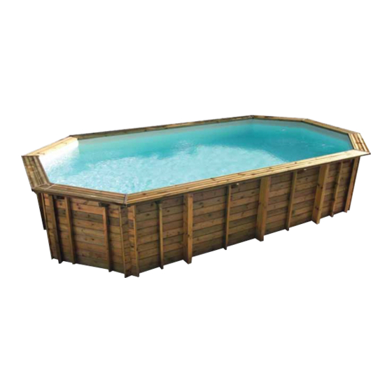
- Page 1 WHITE POOL INSTRUCTION MANUAL pag. 1 / 29 WHITE POOL C.P.A. Assembly and maintenance guide READ CAREFULLY THIS MANUAL AND RETAIN FOR LATER REFERENCE www.cpa-piscine.it Rev.00–16/10/20...
-
Page 2: Table Of Contents
WHITE POOL INSTRUCTION MANUAL pag. 2 / 29 Summary ......................3 IMPORTANT SAFETY INSTRUCTIONS ............................5 COMPONENTS ........................ 7 PHASE 1 – Selecting a suitable site ..........................8 PHASE 2 – Pool setup ........................8 Ground preparation ..........................9 Marking the site ........................ -
Page 3: Important Safety Instructions
WHITE POOL INSTRUCTION MANUAL pag. 3 / 29 IMPORTANT SAFETY INSTRUCTIONS The following instructions contain important safety information, we strongly encourage you to read these important safety instructions and abide by them when using this pool. When installing and using this electrical equipment, basic safety precautions should always be followed, this includes the following. - Page 4 WHITE POOL INSTRUCTION MANUAL pag. 4 / 29 Follow these safety rules: Warning - To avoid electrocution, do not permit electric devices i.e. light, telephone, radio, television, hair dryer, etc. within 2,5 m (8 ft) of this pool. Warning - Risk of electric shock. Never operate any electrical appliance when in the pool or when your body is wet. Warning - Warning - to reduce the risk of injury or hazard, have any damaged cord replaced immediately by the manufacturer, its service agent, or similarly qualified persons.
-
Page 5: Components
M12 x 100 fixing plate maintenance kit connection plate Item No. Description Pool dimension (mm) 8011015 White Pool 490 L4900 x W3600 x H1300 8011012 White Pool 610 L6100 x W3600 x H1300 8011013 White Pool 730 L7300 x W3600 x H1300... - Page 6 WHITE POOL INSTRUCTION MANUAL pag. 6 / 29 white pool 490 white pool 610 white pool 730 white pool 910 Description 8011012 8011012 8011013 8011014 Pool wall Pool liner Ground sheet Top platform 1370mm length Top platform 1460mm length Side top platform...
-
Page 7: Phase 1 - Selecting A Suitable Site
WHITE POOL INSTRUCTION MANUAL pag. 7 / 29 PHASE 1 – Selecting a suitable site Carefully select the site for your new pool. This is the most important decision you will have to make to ensure the safety and success of your pool construction. An incorrect site could cause problems in the future that may cause in jury, death or financial loss. -
Page 8: Phase 2 - Pool Setup
WHITE POOL INSTRUCTION MANUAL pag. 8 / 29 PHASE 2 – Pool setup Ground preparation (Diagram 1) The preparation of the ground is the most important step in the installation of the pool. Diagram 1 www.cpa-piscine.it Rev.00–16/10/20... -
Page 9: Marking The Site
WHITE POOL INSTRUCTION MANUAL pag. 9 / 29 Marking the site Mark the center of the site and drive a stake or screw driver into the soil (see diagram 2). Diagram 2 Tie a piece of string onto the stick. At the other end of the string, tie a funnel. The distance between the stick and the funnel should be 150 mm more than the radius of the pool (see diagram 3). -
Page 10: Levelling The Area
WHITE POOL INSTRUCTION MANUAL pag. 10 / 29 III. Levelling the area WARNING Levelling is extremely important: take as much time as possible to work out a site that is completely firm and levelled. Use a carpenter’s level and straight edge to ensure that the site is completely level, flat and firm (see diagram 5). The pool contains a huge amount of water and thousands of kilos of weight. -
Page 11: Pool Frame Assembly
Unpack all off the components and check the parts against the checklist. See diagram 8, the same L support (21), fixing plate (22) and connection plate (23) are used for below items. Item No. Description Pool dimensions (mm) 8011015 White Pool 490 L4900 x W3600 x H1300 8011012 White Pool 610 L6100 x W3600 x H1300 8011013... - Page 12 Please refer to the layout size of pool you have purchased. WHITE POOL 490 - 8011015 Place the assembled frame upright across the width of the pool at a point 2450mm from the end of the cleared area (see diagram 11).
- Page 13 WHITE POOL INSTRUCTION MANUAL pag. 13 / 29 WHITE POOL 610 – 8011012 WHITE POOL 730 - 8011013 Place the 1st assembled frame upright across the width of the pool at a point 2450 mm from the end of the cleared area. Place the 2nd and the remaining assembled frames at a point 1200 mm from the center line of the adjacent assembled frame (see diagram 12 and 13).
- Page 14 WHITE POOL INSTRUCTION MANUAL pag. 14 / 29 WHITE POOL 910 - 8011014 Place the 1st assembled frame upright across the width of the pool at a point 3070 mm from the end of the cleared area. Place the 2nd and the remaining assembled frames at a point 1480 mm from the center line of the adjacent assembled frame (see diagram 14).
- Page 15 WHITE POOL INSTRUCTION MANUAL pag. 15 / 29 When all the assembled frames are in the correct position, spray paint a line on either side of each assembled frame across the pool. This is to mark out the areas to be excavated. When these areas have been marked out, the assembled frames can be removed from the site.
-
Page 16: Installing Assembled Frames
L support to the star picket with some duct tape. This will hold the post vertical while the cement and backfill is put into place. Note: top of the horizontal L supports and ground should be level. White pool 490 White pool 610 White pool 730... - Page 17 WHITE POOL INSTRUCTION MANUAL pag. 17 / 29 Place the pre-cast concrete blocks under the L supports www.cpa-piscine.it Rev.00–16/10/20...
-
Page 18: Assembling The Pool Base Rails
Important: leave about 1 cm between the 2 ends of the bottom rail. Repeat this process for all bottom rails (see diagram 17). Item No. Description Pool dimension (mm) 8011015 White Pool 490 L4900 x W3600 x H1300 Item No. Description Pool dimension (mm) 8011012... -
Page 19: Fine Adjustment Of The Bottom Rails Diameter
WHITE POOL INSTRUCTION MANUAL pag. 19 / 29 VII. Fine adjustment of the bottom rails diameter When all the rails are slided into the metal pieces, it should form a complete circle and the diameter should be equivalent to the diameter of the pool itself. -
Page 20: Fixing The Pool Wall
WHITE POOL INSTRUCTION MANUAL pag. 20 / 29 VIII. Fixing the pool wall Put the pool wall on a ground cloth, cardboard or a piece of ply wood (see diagram 19). This is to protect the levelled ground while installation of pool wall is taking place. Make sure the square window (for skimmer) is on the upward side. It is advisable to wear protective gloves when handling the metal wall. -
Page 21: Measuring The Pool Wall
WHITE POOL INSTRUCTION MANUAL pag. 21 / 29 Measuring the pool wall WARNING A pool that is not level is very dangerous and may collapse at any time. Diagram 22 Diagram 23 Check the pool wall level by placing a length of timber beam or similar across the diameter of the pool wall and placing the builders level on the top of the timber beam (see diagram 22). -
Page 22: Making A Protective Sand Cushion At The Foot Of The Inner Pool
WHITE POOL INSTRUCTION MANUAL pag. 22 / 29 Making a protective sand cushion at the foot of the inner pool cucitura al centro dell’insenatura pool liner sabbiosa sand cove pool wall bottom rail sand cove Diagram 26 Diagram 27 To protect the liner against the rail and the pool wall, it is recommended to create a protective covering made of fine brick sand at the foot of the pool wall (see diagram 26 and 27). - Page 23 WHITE POOL INSTRUCTION MANUAL pag. 23 / 29 Diagram 30 Diagram 31 Remove the pegs one at time whilst applying the fix rails (see diagram 32). Connect another fix rail, continue around the circle until all fix rails are all joined together. And finally apply the round rails to the fix rails. Diagram 32 Fix all top rails to the top of the pool wall and make sure they are all sitting properly.
-
Page 24: Assembly Of The Resin Vertical Supports
WHITE POOL INSTRUCTION MANUAL pag. 24 / 29 XII. Assembly of the resin vertical supports Line up all the screw holes for the resin vertical supports. The first resin vertical support should be placed over the join in the pool wall. - Page 25 WHITE POOL INSTRUCTION MANUAL pag. 25 / 29 Place a resin top platform over a top metal piece and attach using four bolts. Continue this process until all of the resin top platforms are attached to all of the metal pieces at the top (see diagram 36). Check the alignment but do not tighten. Diagram 36 Fix all resin top platforms to the metal pieces at the top and make sure they are all sitting properly before finally tightening the screws.
-
Page 26: Assembly Of The Joint Protectors
WHITE POOL INSTRUCTION MANUAL pag. 26 / 29 XIII. Assembly of the joint protectors The soft flexi joint covers are for sealing the edges of the resin top platforms. Hook the cover over the inside edge of the resin top platforms and gently pull to fasten the cover to the outside edge. Fix with the screws provided (see diagram 27, 38, 39, 40, 41). -
Page 27: Check All Connections And Joins
WHITE POOL INSTRUCTION MANUAL pag. 27 / 29 XIV. Check all connections and joins Once completed, check all connections and tighten loose screws and bolts but do not over tighten. Replace damaged components and repair all tears, rips and holes with repair patch (see diagram 42). Pool liner Top platform Upper joint protector... -
Page 28: Fixing The Leaf Skimmer
WHITE POOL INSTRUCTION MANUAL pag. 28 / 29 Pool liner Upper joint protector Check for rips tears holes Top platform Check for damaged for and repair where necessary Check for damaged for broken protectos and broken platforms repair replace where necessary where necessary Side top platform Check for damaged for broken platforms... -
Page 29: Phase 4 - Pool Maintenance
WHITE POOL INSTRUCTION MANUAL pag. 29 / 29 PHASE 4 – Pool maintenance 1. Always keep your pool clean and apply the correct pool chemicals. Unsanitary water is a serious health 2. Maintain pool pH level between 7.2 to 7.6 3. - Page 30 SAND FILTER INSTRUCTION MANUAL pag. 1 di 8 SAND FILTER C.P.A. Installation and maintenance manual READ CAREFULLY THIS MANUAL AND RETAIN FOR LATER REFERENCE www.cpa-piscine.it Rev.01–26/04/21...
- Page 31 SAND FILTER INSTRUCTION MANUAL pag. 2 di 8 Warning Prior to assembling and using this product, carefully read and adhere to all caution and important notices located throughout this manual. Failure to comply with these instructions may damage the product or cause serious personal injury or death. Due to the constant technical evolution of this product, we reserve the right to incorporate modifications to the product for its betterment.
- Page 32 SAND FILTER INSTRUCTION MANUAL pag. 3 di 8 The necessary spare parts like the flexible tubes, the metal clips or the filter sand (not included) can be found in the usual service point. Filter/pump installation Before installing the filter pump unit, identify the position in which it is to be installed, as once it has been filled up with sand, the filter is hard to move due to its weight.
- Page 33 SAND FILTER INSTRUCTION MANUAL pag. 4 di 8 Filter parts installation Carefully remove all components from the package and check that nothing is damaged. If the device is damaged, immediately contact the retailer where the purchase was made. Insert the tube with the manifold into the container (drawing 2) and screw the small sand guard filters to the manifold (drawing 3).
- Page 34 SAND FILTER INSTRUCTION MANUAL pag. 5 di 8 Connection of hosepipes to the pump Skimmer circuit: connecting the skimmer to the connection in front of the pump. Vacuum hosepipe: joining the upper connection of the pump to the connection designated ‘PUMP’ on the valve. Return hosepipe: joining the valve connector of the pool.
- Page 35 SAND FILTER INSTRUCTION MANUAL pag. 6 di 8 WARNING The monobloc must not be used without water. The water ensures the cooling. The substitution guarantee does not apply in the case of use without water. Before changing the position of the selector valve, STOP the filtration pump. Multi-way control valve operation The control valve is used to select the 6 different filter functions: filter, rinse, recirculate, backwash, closed and open.
- Page 36 Start the pump again slowly (a start-up too quickly will raise the impurities) and brush the pool floor with the floor cleaner brush. For monobloc without pre-filter, it is better to use a skimmer with a basket and gauze. Monobloc’s data Model Monobloc [mm] [CV] White Pool 490 Ø 300 0,25 White Pool 610 Ø 400 White Pool 730 Ø...
- Page 37 SAND FILTER INSTRUCTION MANUAL pag. 8 di 8 Possible causes of a monobloc malfunction Cause Solution Dirty sand Carry out a Counterwash (wash the sand) The pump sucks air (bubbles in the aspiration) The hosepipe could be defective. Tighten the clips. The water level of the skimmer is low Check the level and raise it if necessary The skimmer basket has moved...
- Page 38 LEAF SKIMMER MANUAL pag. 1 di 3 LEAF SKIMMER C.P.A. Instruction manual READ CAREFULLY THIS MANUAL AND RETAIN FOR LATER REFERENCE www.cpa-piscine.it Rev.00–16/10/20...
- Page 39 LEAF SKIMMER MANUAL pag. 2 di 3 Components Description Quantity Hose attachment Cover Basket Skimmer housing Weir Gasket Face plate cover Screw ST5.5x25 Skimmer conncector Inlet connector kit Teflon tape Stop water plug www.cpa-piscine.it Rev.00–16/10/20...
- Page 40 LEAF SKIMMER MANUAL pag. 3 di 3 Installation Inlet and outlet hose connection kit installation Follow the metal wall pool manual for cutting the holes for the inlet, outlet and skimmer box housing connections. Fill the pool with water between 3 to 6 cm below the position of the inlet connector kit hole (see diagram 1). Screw the inlet connector.