Advertisement
Quick Links
Important Notes
This Scanstrut Mast Bracket is only designed to support Radomes as stated in Scanstrut Product Guide, under normal sailing conditions.
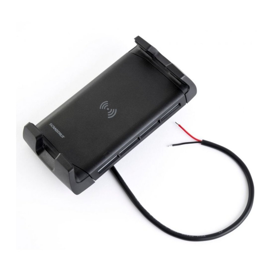
ROKK Wireless - Active (SC-CW-04E)
Use of the bracket with unapproved products, or overloading, invalidates any bracket warranty.
No liability is accepted for damage caused by incorrect installation.
Technical information.
Product has been designed speci cally for the mounting of approved radar under normal sailing conditions.
Product is designed to become detached from the mast in the event of an overload or other abuse, for example, impact, excessive force and entanglement in sails or rigging.
Input voltage range :
The safety lanyard must be tted according to the instructions. Failure to do so invalidates any bracket warranty.
Input current max:
Output power:
Mast bracket must be regularly inspected for evidence of damage or loose parts.
Standby current draw:
This product is designed to suit aluminium masts with a wall thickness in the range 2mm (5/64") - 5mm (3/16"). For installation on non-aluminium masts, or mast sections outside the above
Waterproof rating:
sizes, please consult your mast manufacturer.
Certi cations:
The assembly is not designed to be fully removed and re-installed once tted. I
For latest tech info visit: www.scanstrut.com/rokk-wireless
f bracket needs to be removed for servicing, the bracket should be disassembled from the feet by removing the bolts. The feet must remain attached to the mast, and the bracket must be
re- tted to the original feet, in their original location.
READ IMPORTANT SAFETY INFORMATION
LEAFLET BEFORE INSTALLING.
Parts list.
This ROKK wireless charger is only designed to be tted to a 12/24V system (9-32V input). Connecting this product to a voltage supply which is greater than speci ed may cause irriversible
samage to the product.
ROKK Wireless
An appropriate fuse must be used inline between the battery and the product to protect the power supply. @9V and @18V (ASK CHARLES TO RECCOMEND)
The cable must be attached to the underside surface to ensure the product does not loosen during vibration loading.
No liability is accepted for damage caused by incorrect installation.
Product has been desgined speci cally for the charging of Qi compatible devices.
The grippy surface does not ensure the device will not slip during extreme opetating environments such as high accelration and deceleration.
Installation jig
If a phone case which is thicker than 3mm is used it may cause the product to fail temporarily., this is a safety feature which protects the electronics from over-heating.
No. 4 x 3/4" (18mm)
When used in a high ambient temperature the product may temporarily fail, this is a safety feature which protects the electronics from over-heating. This safety feature may also been seen on
self-tapping screw
the phone where it will stop taking charge, this is common for all smart phone devices.
This product must be installed according to the instructions provided. Failure to do so could result in personal injury or damage to the product and surrounds.
Scanstrut reccomends the installation to be carried out by a professional electrician.
This product is not approved for use in hazardous or ammable environments.
The power supply muct be switched o before installing the product.
DRILLING TEMPLATE
SCALE 1:1
Check Scale 50mm
37mm
(1.5")
31mm
(1.2")
Scanstrut Ltd.
10-30V DC (12/24V system)
1.5A
5W (5V, 1A)
< 0.03W
IPX6 front and back
Qi, CE, FCC, ROHS,
UNECE R10 E24
Tools required.
Pozi screwdriver
Active
6mm (0.24") drill bit
x1
Drill bit (for pilot hole)
Material
Soft Material
E.g plywood
x1
Hard Material
E.g Fiberglass
acrylic, hardwood
x4
37mm
(1.5")
5 Darts Business Park Clyst st George Exeter EX3 0QH
E-mail:
sales@scanstrut.com
18-01-2020 (Issue 8)
1
Retain installation jig to use in step 2.
4a
Ensure installation area is at.
No. 4 Screw
2mm
(5/64")
2.5mm
(3/32")
4b
Ensure ROKK Active is vertical.
6
- Feed cable through the hole.
- Apply sealant to x4 screws.
- Screw product in place.
- Remove installation jig.
7
Website:
www.scanstrut.com
Installation instructions.
2
3
Ensure there is suf cient clearance in chosen
installation area.
5
Use drilling template to drill ø6mm (0.24")
cable hole and x4 pilot holes
(see tools required table).
Connect wires to 12/24V supply,
ensuring a waterproof connection. Fuse
according to input voltage and current.
Tel:
+44(0)1392 531280
Insert the installation jig.
205mm
(8")
Advertisement

Related Manuals for Scanstrut ROKK SC-CW-04E


Summary of Contents for Scanstrut ROKK SC-CW-04E
- Page 1 Important Notes 18-01-2020 (Issue 8) This Scanstrut Mast Bracket is only designed to support Radomes as stated in Scanstrut Product Guide, under normal sailing conditions. ROKK Wireless - Active (SC-CW-04E) Installation instructions. Use of the bracket with unapproved products, or overloading, invalidates any bracket warranty.
- Page 2 Before drilling any holes, ensure the area behind the mounting location is clear of wires, fuel and all other hazardous objects. Scanstrut Ltd. accepts no responsibility for any injuries or other damages arising from the use of their products in any circumstances.
Need help?
Do you have a question about the ROKK SC-CW-04E and is the answer not in the manual?
Questions and answers