Table of Contents
Advertisement
Quick Links
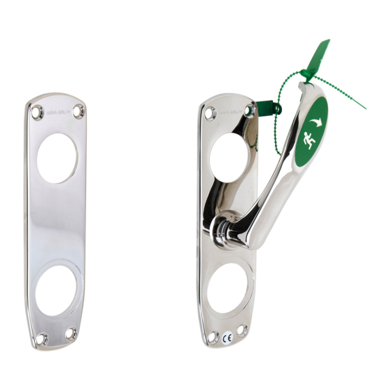
This mounting instruction is intended for installation of emergency exit device Assa 179A
with following ordering numbers:
815516, 815517, 815518, 815519, 815520, 815521,815522, 815523, 815524 and 815528 in
combination with Assa lock case model 710-50 with ordering number 357711.
The safety features of this product are essential to its compliance with EN 179.
No modification of any kind, other than those described in these instructions, are permitted.
Assa takes no responsibility for products not mounted as described in these instructions or if
enclosed maintenance and operating instruction not are followed.
In compliance with EN 179 the Assa 179A is intended for use on single doors with following
size:
Product
179A
179A-2
Assa 179A must be installed together with Assas strike plate model 1487 with following
ordering numbers: 357545, 357546, 357547, 357548 and 357549.
Assa 179A can be installed together with following outside modular profile accessories:
- Round or oval cylinder with Scandinavian shape.
- Any handle suitable for Scandinavian lock case under premises that the handle do not affect
the latch door-holding properties for a door in a fire cell.
Assa AB 702031 Edition 1
Mounting instruction
Emergency exit device Assa 179A
Warning!
Ordering
Max width of
number
815516
1100 mm
815517
815518
815519
815520
815521
1100 mm
815522
815523
815524
815528
Page 1 of 4
Max height of
door
door
2100 mm
2100 mm
Max weight
of door
100 kg
100 kg
Advertisement
Table of Contents

Subscribe to Our Youtube Channel
Related Manuals for Assa Abloy 179A


Summary of Contents for Assa Abloy 179A
- Page 1 Assa takes no responsibility for products not mounted as described in these instructions or if enclosed maintenance and operating instruction not are followed. In compliance with EN 179 the Assa 179A is intended for use on single doors with following size:...
- Page 2 1. Use drill template 700538 and drill 4 holes (Ø 10 mm) for the bolt through fixing. Also drill a hole (Ø 40-42 mm) for the exit handle. 2. Install lock case Assa 710-50 and the strike plate. Assa AB 702031 Edition 1 Page 2 of 4...
- Page 3 3. Ensure that the arrows of the lock case cylinder follower points downwards (6 o’clock) on both sides. Attach the cylinder. NOTE! Functional disorder may occur in the lock case if the cylinder is operated with the cylinder followers in wrong position. 4.
- Page 4 6. Attach the handle and cylinder accessories. 7. Test the function with the dead bolt in a locked position and by pressing the exit handle downwards. Both dead bolt and latch shall then retract and the door shall be possible to open. After opening procedure the exit handle shall easily return to its starting position.
- Page 5 Maintenance and operating instruction for Emergency exit device Assa 179 A / B Emergency exit device Regular intervals of at least: One month Check all fastenings, screws etc and that the exit handle operates in good order. Open the door by pressing the exit handle downwards. Both dead bolt and latch(es) shall then retract and the door shall be possible to open.
Need help?
Do you have a question about the 179A and is the answer not in the manual?
Questions and answers