Table of Contents
Advertisement
Quick Links
Installation Instructions
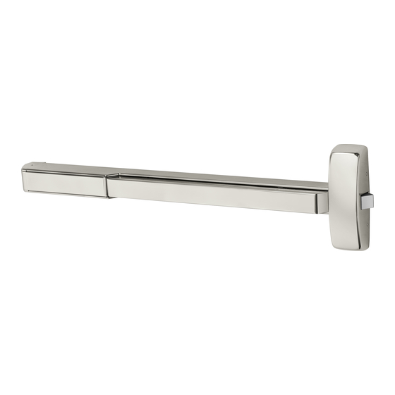
PE8600 Series (12-MD, MD, & AD)
Concealed Vertical Rod Exit Devices
WARNING
This product can expose you to
lead which is known to the state of
California to cause cancer and birth
defects or other reproductive harm.
For more information go to www.
P65warnings.ca.gov.
1-800-727-5477 • www.sargentlock.com
Copyright © 2023, SARGENT Manufacturing Company. All rights reserved. Reproduction in whole or in part without the express written
permission of SARGENT Manufacturing Company is prohibited. Patent pending and/or patent www.assaabloydss.com/patents.
WARNING
Attention Installer: Improper
installation may result in damage
to the product and void the factory
warranty.
A8305-1 5/23
Advertisement
Table of Contents

Related Manuals for Assa Abloy Sargent AD-PE8600


Summary of Contents for Assa Abloy Sargent AD-PE8600
- Page 1 Installation Instructions PE8600 Series (12-MD, MD, & AD) Concealed Vertical Rod Exit Devices WARNING WARNING This product can expose you to Attention Installer: Improper lead which is known to the state of installation may result in damage California to cause cancer and birth to the product and void the factory defects or other reproductive harm.
-
Page 2: Screw Chart
PE8600 Series (12-MD, MD, & AD) Concealed Vertical Rod Exit Devices Installation Instructions Screw Chart TOTAL QTY SCREW WHERE USED SUPPLIED (4) CHASSIS CORNER MOUNTING HOLES #10-24 X 3/4" FLAT HEAD MACHINE SCREW (2) REAR MOUNTING PLATE #10-24 X 3/4" ROUND HEAD MACHINE SCREW (1) INNER CHASSIS TOP MOUNTING HOLE... -
Page 3: Equipment Needed
PE8600 Series (12-MD, MD, & AD) Concealed Vertical Rod Exit Devices Installation Instructions Equipment Needed Tools Support Block (Provided) Rail Cutting Guide (Provided) Strike Packs Strike Pack for AD-PE8400 Strike Pack for 12-MD-PE8400 AD-PE8600 Strike Pack for MD-PE8400 MD-PE8600 12-MD-PE8600 640 TOP AND B OTTOM S TR IKE #10 X 1/2"... - Page 4 PE8600 Series (12-MD, MD, & AD) Concealed Vertical Rod Exit Devices Installation Instructions Template AD-PE8600, NB-AD-PE8600 & NB-MD-PE8600, MD-PE8600, 12-MD-PE8600 MINIMUM CLEAR C L OF RODS OPENING FOR INSERTING DEVICE OPENING FOR INSERTING DEVICE TOP OF DOOR .150 10-24 UNC - 2B .350 ONLY FOR LHRB .187...
-
Page 5: Exploded View
PE8600 Series (12-MD, MD, & AD) Concealed Vertical Rod Exit Devices Installation Instructions Exploded View Top Chassis THIS EXIT DEVICE IS HANDED CHECK HAND OF DEVICE AGAINST APPLICATION Top Bolt OUTSIDE RIGHT HAND LEFT HAND REVERSE REVERSE BEVEL BEVEL INSIDE Rod silencer Mounting Plate Center case chassis... - Page 6 PE8600 Series (12-MD, MD, & AD) Concealed Vertical Rod Exit Devices Installation Instructions Remove door from frame, and prepare the door per template. A8305-1 5/23 1-800-727-5477 • www.sargentlock.com Copyright © 2023, SARGENT Manufacturing Company. All rights reserved. Reproduction in whole or in part without the express written permission of SARGENT Manufacturing Company is prohibited.
- Page 7 PE8600 Series (12-MD, MD, & AD) Concealed Vertical Rod Exit Devices Installation Instructions Top bolt and rod assembly *Bottom bolt and rod assembly Screw top bolt and rod assembly and bottom bolt and rod assembly into the inner chassis. *Bottom bolt rod and assembly will not be used with NB devices.
- Page 8 PE8600 Series (12-MD, MD, & AD) Concealed Vertical Rod Exit Devices Installation Instructions Top bolt teeth Feed rod and inner chassis assembly into the door. Ensure teeth face down and top bolt teeth are opposite the inside door prep. A8305-1 5/23 1-800-727-5477 •...
- Page 9 PE8600 Series (12-MD, MD, & AD) Concealed Vertical Rod Exit Devices Installation Instructions FILLISTER HEAD SCREW #10-24 x 3/8” FLAT HEAD SCREW #10-24 x 1/2” Attach inner case chassis to the door with (1) #10-24 x 1/2” flat head screw (HH) and secure with (1) #10-24 x 3/8”...
- Page 10 PE8600 Series (12-MD, MD, & AD) Concealed Vertical Rod Exit Devices Installation Instructions Adjusting the top bolt and rod assembly • 1/8” gap or less between door top and frame: Rotate bolt to make it even with the top of the door. •...
- Page 11 PE8600 Series (12-MD, MD, & AD) Concealed Vertical Rod Exit Devices Installation Instructions Rod silencer Slide rod silencer over the top bolt onto rod, followed by top case. Secure top case with (2) #10-24 x 3/8 oval head screws (DD). A8305-1 5/23 1-800-727-5477 •...
- Page 12 PE8600 Series (12-MD, MD, & AD) Concealed Vertical Rod Exit Devices Installation Instructions For AD- application For MD- and 12-MD- application For AD-PE8600 Bottom Bolt For MD-PE8600 & 12-MD-PE8600 Install bottom plate over Bottom Bolt the bottom bolt and Install bottom plate over secure with two #10-24 x 3/8"...
- Page 13 PE8600 Series (12-MD, MD, & AD) Concealed Vertical Rod Exit Devices Installation Instructions • For MD-PE8600 and 12-MD-PE8600: Attach 650 strike to frame with (2) #10-24 x 1/2” flat head screws. • For AD-PE8600: Attach 640 strike to frame with (2) #10-24 x 1/2” flat head screws. A8305-1 5/23 1-800-727-5477 •...
- Page 14 PE8600 Series (12-MD, MD, & AD) Concealed Vertical Rod Exit Devices Installation Instructions • For MD-PE8600: Attach 650 bottom strike to floor with anchors and supplied fasteners. • For 12-MD-PE8600 attach 606 bottom strike to floor with anchors and supplied fasteners. •...
- Page 15 PE8600 Series (12-MD, MD, & AD) Concealed Vertical Rod Exit Devices Installation Instructions Rail cutting guide If the rail doesn’t need to be cut, continue to page 17 step 12. If the rail must be cut, follow these steps on page 15 and 16: Refer to the individual exit device installation instructions for rail cutting requirements / restrictions.
- Page 16 PE8600 Series (12-MD, MD, & AD) Concealed Vertical Rod Exit Devices Installation Instructions Rail cutting guide, continued. Cut line C. Ensure plastic insert support is installed under D. Wrap the rail and insert in masking tape, the cut line. as shown. Rail Cutting Guide Cut line Place the rail cutting guide over the masking tape and align it with the cut line.
- Page 17 PE8600 Series (12-MD, MD, & AD) Concealed Vertical Rod Exit Devices Installation Instructions Slide the rail assembly on the chassis. Ensure rail carrier tabs are aligned with Tighten chassis mounting screws. chassis. Ensure mounting rail bracket is against Insert the mounting bracket in the end of the the rail without a gap.
- Page 18 PE8600 Series (12-MD, MD, & AD) Concealed Vertical Rod Exit Devices Installation Instructions Drill and tap end cap bracket holes #10-24 Level the rail and mark mounting holes, using the (2 Places). bracket as a guide. Atttach mounting bracket and secure rail as- sembly to door with #10-24 x 3/4”...
- Page 19 PE8600 Series (12-MD, MD, & AD) Concealed Vertical Rod Exit Devices Installation Instructions TOP BOLT ADJUSTMENT BOTTOM BOLT ADJUSTMENT If adjustments are needed, before closing the door check the following: • Push rail in to retract bolts. • Bolts stay retracted (hold back). •...
-
Page 20: Check For Proper Operation
Check for proper operation. Install chassis and end cap cover, using supplied #8-32 x 5/16 oval head screws (CC). 1-800-727-5477 • www.sargentlock.com Copyright © 2023, SARGENT Manufacturing Company. All rights reserved. Reproduction in whole or in part without the express written permission of SARGENT Manufacturing Company is prohibited.
Need help?
Do you have a question about the Sargent AD-PE8600 and is the answer not in the manual?
Questions and answers