
Related Manuals for Lincoln Electric SPEEDTEC 215C AUS


Summary of Contents for Lincoln Electric SPEEDTEC 215C AUS
- Page 1 IM3065 10/2020 REV02 SPEEDTEC 215C AUS OPERATOR’S MANUAL ENGLISH Lincoln Electric Bester Sp. z o.o. ul. Jana III Sobieskiego 19A, 58-260 Bielawa, Poland www.lincolnelectric.eu...
-
Page 2: Table Of Contents
12/05 THANKS! For having choosen the QUALITY of the Lincoln Electric products. Please Examine Package and Equipment for Damage. Claims for material damaged in shipment must be notified immediately to the dealer. For future reference record in the table below your equipment identification information. Model Name, Code & Serial Number can be found on the machine rating plate. -
Page 3: Technical Specifications
Technical Specifications NAME INDEX SPEEDTEC 215C AUS K14146-2 INPUT Input Voltage U 230 Vac ± 10%, 1-phase 115 Vac ± 10%, 1-phase Frequency 50/60 Hz Input Amperes I 1max Input Power at Rated Cycle (40°C) 6,2kVA @ 25% Duty Cycle 2,6kVA @ 40% Duty Cycle cos φ... -
Page 4: Electromagnetic Compatibility (Emc)
If any electromagnetic disturbances are detected the operator must put in place corrective actions to eliminate these disturbances with, if necessary, assistance from Lincoln Electric. Before installing the machine, the operator must check the work area for any devices that may malfunction because of electromagnetic disturbances. -
Page 5: Safety
Failure to follow the instructions in this manual could cause serious personal injury, loss of life, or equipment damage. Read and understand the following explanations of the warning symbols. Lincoln Electric is not responsible for damages caused by improper installation, improper care or abnormal operation. - Page 6 WELDING SPARKS CAN CAUSE FIRE OR EXPLOSION: Remove fire hazards from the welding area and have a fire extinguisher easily accessible. Welding sparks and hot materials from the welding process can easily go through small cracks and openings to adjacent areas. Do not weld on any tanks, drums, containers, or material until the proper steps have been taken to insure that no flammable or toxic vapors will be present.
-
Page 7: Introduction
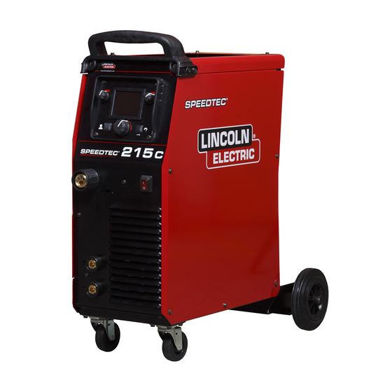
Introduction General Description Gas regulator Gas hose – 2m The welding machines SPEEDTEC 215C enables Driving roll V0.8/V1.0 for solid wire (mounted in the welding: wire feeder) GMAW (MIG/MAG) Bracket for gas bottle 230mm (SP215C). ... - Page 8 settings is changed by this knob. Controls and Operational Features 10. Right Knob: The value of parameter in the upper right side of display [2] is adjusted. Figure 1. Left Knob: The value of parameter in the upper left side of display [2] is adjusted. Figure 2.
- Page 9 WARNING 15. Welding Wire (for GMAW / FCAW-SS). Positive (+) polarity is set at the factory. 16. Terminal Block of Changing Polarity (for GMAW / WARNING FCAW-SS process): This terminal block enables to Before welding check the polarity for using electrodes and set the welding polarity (+ ;...
- Page 10 Table 1 WORK LEAD Table 2 WORK LEAD English English...
- Page 11 Loading the Electrode Wire WARNING Turn the machine off. If the roll pressure is too low the roll will slide on the wire. Open the side cover of the machine. If the roll pressure is set too high the wire may be ...
- Page 12 Gas Connection Preparation the Machine for Welding Shield gas is required for welding GMAW and GTAW GMAW and FCAW-SS Process. process. Gas flow regulator and gas hoses have been Procedure of begin welding of GMAW or FCAW-SS added to SPEEDTEC 215C. Once a gas cylinder with a process: flow regulator has been securely installed, connect the ...
- Page 13 Spot Timer adjusts the time welding will continue even if Spot Timer adjusts the time welding will continue even if the trigger is still pulled. This option has no effect in 4-Step the trigger is still pulled. This option has no effect in 4-Step Trigger Mode.
- Page 14 Turn the machine on. than 10 minutes, sleep mode is actrivated to save power. Set the welding parameters. During Sleep Mode logo “Lincoln Electric” moves onto the display [2]. The welding machine is now ready to weld. WARNING Do not kink or pull cable around sharp corners.
- Page 15 Guide’s Marking Interface SPEEDTEC 215C Description of the user interface in "Quick Guide" chapter Voltage Reduction Select Welding Process SMAW (MMA) Welding Device active (GTAW / SMAW only) GMAW (MIG/MAG) Burnback Brightness Level Manual Welding View Software FCAW- Self shielded Run-in WFS Hardware Version...
- Page 16 We respond to our customers based on the best personnel will cause, that the manufacturer’s warranty will information in our possession at that time. Lincoln Electric become null and void. is not in a position to warrant or guarantee such advice,...
-
Page 17: Weee
12/05 Part List reading instructions Do not use this part list for a machine if its code number is not listed. Contact the Lincoln Electric Service Department for any code number not listed. Use the illustration of assembly page and the table below to determine where the part is located for your particular code machine. -
Page 18: Quick Guide
Quick Guide English English... - Page 19 English English...
- Page 20 English English...
-
Page 21: Accessories
Accessories K10429-15-xM The gas-cooled gun LGS150 to GMAW process - 3m K10513-17-4V GTAW torch - 4m E/H-200A-25-3M Welding cable with electrode holder to SMAW process - 3m K14010-1 Work Lead -3m KIT-200A-25-3M Lead’s KIT to SMAW process: The electrode holder with lead to SMAW process - 3m ...
Need help?
Do you have a question about the SPEEDTEC 215C AUS and is the answer not in the manual?
Questions and answers