Advertisement
INDEX
PAGE
1
REMOVABLE ITA BACKSHELL
2
ENGAGEMENT OF ITA WITH RECEIVER
3
KEYING PIN KIT USAGE INSTRUCTIONS
4
CABLE BUNDLE WIRE INFORMATION
5
VERTICAL HINGED MOUNTING FRAME DRAWINGS
6
G6 RECEIVER MOUNTING SPECIFICATIONS
7
G10 RECEIVER MOUNTING SPECIFICATIONS
8
G10 RECEIVER PANEL CUT OUT DRAWING
9
PRECAUTIONARY NOTES/ TROUBLESHOOTING
Please note that any printed or downloaded User Manuals may not reflect the most current revisions.
The information contained in these manuals is subject to change.
For the most current information available, visit vpc.com.
(CLICK TO NAVIGATE TO PAGE)
G6 & G10 USER MANUAL
3/2/21
Advertisement
Table of Contents

Subscribe to Our Youtube Channel
Related Manuals for VPC G6 ITA

Summary of Contents for VPC G6 ITA
- Page 1 G10 RECEIVER PANEL CUT OUT DRAWING PRECAUTIONARY NOTES/ TROUBLESHOOTING Please note that any printed or downloaded User Manuals may not reflect the most current revisions. The information contained in these manuals is subject to change. For the most current information available, visit vpc.com. 3/2/21...
- Page 2 G6 has one. Once the backshell is put back in place be sure to secure the screw(s) back in place as the EMI shielding provided by the backshell will not take effect otherwise. For drawings, specs and more information on the G6 and G10, please visit vpc.com. RETURN TO INDEX For more information visit vpc.com...
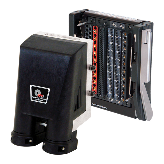
- Page 3 G6 & G10 USER MANUAL ENGAGEMENT OF ITA WITH RECEIVER G6 ITA • PART # 410 104 273, 410 104 331 G6 RCV • PART # 310 104 318 G10 ITA • PART # 410 104 272, 410 104 375 G10 RCV •...
- Page 4 PIN B PIN D SCREW B SCREW D OPEN INSTALLED INSTALLED OPEN OPEN INSTALLED INSTALLED OPEN Additional details can be found by accessing the drawing for this part number online at vpc.com. RETURN TO INDEX For more information visit vpc.com 3/16/21...
- Page 5 G6 & G10 USER MANUAL CABLE BUNDLE WIRE INFORMATION G6 ITA • PART # 410 104 273 G10 ITA • PART # 410 104 272 Max Oblong Cable Opening Diameter= 1.59” The formula below can be used to calculate the maximum number of wires recommended for a cable bundle used with a max cable exit of 1.59”.
- Page 6 VERTICAL HINGED MOUNTING FRAME, G10, 5U• PART # 310 113 342 VERTICAL HINGED MOUNTING FRAME, G6, 5U• PART # 310 113 341 G10, 5U• PART # 310 113 342 G6, 5U• PART # 310 113 341 RETURN TO INDEX For more information visit vpc.com 3/16/21...
- Page 7 G6 & G10 USER MANUAL RECEIVER MOUNTING SPECIFICATIONS G6 RCV • PART # 310 104 318 RETURN TO INDEX For more information visit vpc.com 3/16/21...
-
Page 8: Mounting Specifications
G6 & G10 USER MANUAL MOUNTING SPECIFICATIONS RECEIVER, G10, 10 MODULE • PART # 310 104 317 RETURN TO INDEX For more information visit vpc.com 3/16/21... -
Page 9: Panel Cutout
G6 & G10 USER MANUAL PANEL CUTOUT RECEIVER, G10, 10 MODULE • PART # 310 104 317 RETURN TO INDEX For more information visit vpc.com 3/16/21... -
Page 10: Precautionary Notes
• Follow all steps above for an unaligned ITA frame, if force is still needed please contact VPC for assistance. ITA will not engage with the receiver after diagnosing the above problems •...
Need help?
Do you have a question about the G6 ITA and is the answer not in the manual?
Questions and answers