Table of Contents
Advertisement
Quick Links
General Description
The epc600 Camera Spot is a fully assembled and tested TOF
Range Finder camera to be used with the epc600/610 Evaluation
Kit.
The module includes an epc600 TOF Range Finder chip, an active
IR LED illumination for the observation area, a complete lens sys-
tem and a cable interface to the mainboard. This allows for a flexi-
ble and convenient placement in a lab setup. The module has a
1.4° x 1.4° optical aperture angle.
In combination with the epc600/610 Evaluation Kit (which provides
all hardware to operate the epc600 Range Finder module), the
user has a fully functional TOF evaluation system.
The included application software enables the user to explore the
TOF Range Finder technology as well the epc600 Range Finder
chip.
Overview
Figure 1: Field of view of the camera
Receiver spot:
Emitter spot:
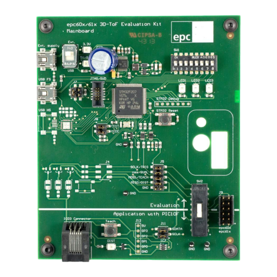
Figure 3: The evaluation system hardware
© 2014 ESPROS Photonics Corporation
Characteristics subject to change without notice
Time-of-flight epc600 camera, 1 pixel, spot angle view
50 x 50 mm (1.4° x 1.4°)
99mm diameter ≙ □ 70 x 70mm
Manual – epc600 Camera Spot
Features
■ Fully functional TOF Range Finder camera with a 1 pixel epc600
imager chip.
■ Comprehensive application software with a graphical user inter-
face to operate the epc600 chip in the camera module.
■ Automatic mode to measure distances with adaptive integration
times.
■ Manual mode to run the camera in an individual set-up or to ana -
lyze the raw data.
■ Possibility to store and reload operating configurations.
■ Functionality for logging measurement data on a PC.
Purpose
■ Performance analysis of the epc600 chip in terms of speed, oper -
ating range and accuracy.
■ Demonstration and evaluation of the hard- and software.
■ Development environment for user specific epc600 chip applica -
tions.
Figure 2: The camera module
Figure 4: Main dialog of the graphical user inter face
1 / 22
Manual epc600_Camera - V1.6
www.espros.ch
Advertisement
Table of Contents

Related Manuals for EPC epc600


Summary of Contents for EPC epc600
-
Page 1: General Description
TOF Range Finder technology as well the epc600 Range Finder Purpose chip. ■ Performance analysis of the epc600 chip in terms of speed, oper - ating range and accuracy. ■ Demonstration and evaluation of the hard- and software. ■ Development environment for user specific epc600 chip applica - tions. - Page 2 IMPORTANT INFORMATION SAFETY ADVICE DO NOT LOOK DIRECTLY INTO THE CAMERA UNDER OPERATION ! Depending on the mode of operation, the camera device emits highly concentrated non-visible infrared light. It can be hazardous to the human eye. The use of these devices has to follow the safety precautions given in IEC 60825-1 and IEC62471. THIS EVALUATION KIT SHOULD ONLY BE INSTALLED AND USED BY AUTHORIZED AND FULLY TRAINED PEOPLE.
-
Page 3: Table Of Contents
4.1.1. SW installation on PC..................................11 4.1.2. SW installation on Mac..................................12 4.2. Running the epc600 application ................................12 5. Software “epc600 evaluation system” and user interface ........................14 5.1. Overview......................................14 5.1.1. User Interface Overview................................... 14 5.1.2. Basic operation....................................15 5.1.3. -
Page 4: General Overview Of The Epc600/610 Evaluation Kit
1. General overview of the epc600/610 Evaluation Kit The chapter gives an overview about the epc600/610 Evaluation Kits, their components and the technical data for this module. 1.1. Ordering information Part number Order information Description Kits P100 110 epc600 Evaluation Kit Spot Evaluation kit set with an epc600 TOF Range Finder chip –... -
Page 5: System Requirements For Host Pc
CE regulations. RoHS Fulfills 2002/95/EC Table 3: Technical data epc600 Camera 1.5. Support and technical contact If you need more information, please contact us at info@espros.ch. © 2014 ESPROS Photonics Corporation 5 / 22 Manual epc600_Camera - V1.6... -
Page 6: Hardware
2. Hardware The purpose of this section is to introduce to the user the epc600 camera module and the functional use of the epc600/610 Evaluation Kit. 2.1. Block diagram The system consists of 3 main parts: A personal computer, the Evaluation Kit mainboard and a camera module (refer to Figure 6). - Page 7 ■ Supports the user during development and testing of his own hard- and software. Exceptions of this kit: ■ The kit is a demonstrator. It is not designed for verification of datasheet parameters. Such tests need a dedicated test environment. ■...
-
Page 8: Schematics
2.2. Schematics © 2014 ESPROS Photonics Corporation 8 / 22 Manual epc600_Camera - V1.6 Characteristics subject to change without notice www.espros.ch... -
Page 9: Assembly & Part List
2.4. Hardware of the camera The electronics of the camera module contains the epc600 chip, the buffering of the supply voltage, the crystal for the chip clock, two IR emitter LEDs and a connector for the cable to the mainboard. The housing incorporates the emitter and receiver lenses. It minimizes opti - cal crosstalk. -
Page 10: Evaluation Kit Mainboard
VDDT: Connect to +5V Table 5: Pin assignment camera connector J1 3. Evaluation Kit mainboard For the technical description of the Evaluation Kit mainboard, refer to “Manual – epc600/610 Evaluation Kit – mainboard”. © 2014 ESPROS Photonics Corporation 10 / 22 Manual epc600_Camera - V1.6... -
Page 11: Setup & Installation
Start the application with the link “epc60x Evaluation Kit” that has been added to your program shortcut menu. Disconnect the USB cable before attaching a camera module and proceed with chapter 4.2. Running the epc600 application . Switch to “USB”... -
Page 12: Sw Installation On Mac
Before you start the installation process, close all running applications. Copy the installer file “epc600 epc610 Evaluation Kit Install_Vx.x.pkg” from the CD to the desktop. Start the installation by executing the in - staller “epc600 epc610 Evaluation Kit Install_Vx.x.pkg”. The installer routine will load the application software as well as the necessary drivers on your system. - Page 13 Set the operation switch SW2 to “Evaluation”. (See Figure 13). This will set the evaluation system into the epc600 evaluation mode and al- lows for the operation through the application software on the computer. Connect with the USB cable the computer to the Evaluation Board. The board is now powered up by USB.
-
Page 14: Software "Epc600 Evaluation System" And User Interface
This chapter describes the epc600/610 Evaluation Kit software (SW) and graphical user interface (GUI). The user interface is designed as a dialog based application. The software operates the epc600 camera module, reads the data delivered by the module and allows for data logging. -
Page 15: Basic Operation
Area Description Distance & Amplitude Shows the measured distance and amplitude. Real time values as well as statistical figures are displayed. dialog Integration time dialog The dialog holds the switch that allows for either the setting of the the integration time manually or to have the internal algorithm automatically set the integration time. -
Page 16: Distance And Amplitude Dialog
1.6μs / 12.5μs / 205μs. The integration time corresponding to the selected values is displayed in real time and is continuously adjust - ed to get the optimal measurement result. Refer to the epc600 datasheet for more information on integration time and how to adjust it. -
Page 17: Distance Range Settings
5.1.5. Distance range settings The settings here affect only the user interface and do not have any influence on the epc600 chip. They are intended to set a fixed offset value and “zoom” in on an operational point. The “zoom” effect will become visible on the range bar of the distance and amplitude dialog. -
Page 18: Application Settings
Figure 22: Application settings 5.1.10. Log dialog This function allows data logging for offline analysis of epc600 chip read-out data as well as corrected data. The data stream can be col- lected either by number of measurement counts or by a logging time. -
Page 19: Additional Technical Info And Definitions
6.1. Illumination Good illumination is crucial, as is the design of the Rx and Tx lens system. epc provides several application notes on this topic. However, an LED illumination subsystem and the matching Rx and Tx lens systems requires adequate experience. -
Page 20: Temperature Compensation
- ture is necessary. The epc600 has internal temperature sensors that can be used for such compensations. For more details, refer to the datasheet of the chip. -
Page 21: Light Scattering
8. Addendum 8.1. Related documents ■ Manual – epc600/610 Evaluation Kit – mainboard, ESPROS photonics corp., 2014 ■ epc600 datasheet, ESPROS photonics corp., 2014 ■ STM32F205xx, STM32F207xx, STM32F215xx and STM32F217xx advanced ARM-based 32-bit MCUs, Reference manual, ST Micro- electronics corp., 2011... -
Page 22: Important Notice
(such as life support) where a failure of the epc product would reason - ably be expected to cause severe personal injury or death, unless officers of the parties have executed an agreement specifically govern- ing such use.
Need help?
Do you have a question about the epc600 and is the answer not in the manual?
Questions and answers