
Subscribe to Our Youtube Channel
Related Manuals for Vents VUT 800 WH


Summary of Contents for Vents VUT 800 WH
- Page 1 USER’S MANUAL VUT 800 WH VUT 1000 WH VUT 1500 WH VUT 2000 WH HEAT RECOVERY AIR HANDLING UNIT...
-
Page 2: Table Of Contents
CONTENTS Safety requirements Introduction Delivery set Designation key Technical data Unit design and operating logic Mounting and set-up Condensate drainage Functional diagram Connection to power mains Unit control Maintenance Fault handling Storage and transportation rules Manufacturer's warranty Acceptance certificate Seller information Connection certificate Warranty card... -
Page 3: Safety Requirements
SAFETY REQUIREMENTS Read the user’s manual carefully prior to the operation and installation of the heat recovery air handling unit. Fulfill the operation manual requirements as well as the provisions of all the applicable local and national construction, electrical and technical codes and standards. - Page 4 Use the unit only as intended Do not touch the unit controls by the manufacturer. with wet hands. Do not connect a clothes dryer Do not carry out the unit or other similar equipment maintenance with wet hands. to the unit or the ventilation system.
-
Page 5: Introduction
This user’s manual includes technical description, operation, installation and mounting guidelines, technical data for the heat recovery air handling unit VENTS VUT … WH, hereinafter referred as the unit. The unit is designed to ensure continuous mechanical air exchange in houses, offices, hotels, cafés, conference halls, and other utility and public spaces as well as to recover the heat energy contained in the air extracted from the premises to warm up the filtered stream of supply air. -
Page 6: Technical Data
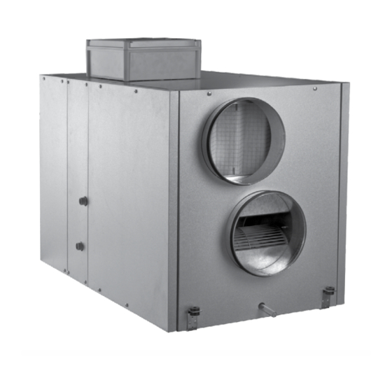
The unit overall and connecting dimensions, external view, technical data are shown in Fig. 1 and in Tables 1 and 2. The unit design is regularly improved, so some models can slightly differ from those ones described in this manual. Fig. 1. Overall and connecting dimensions Table 1 Model VUT 800 WH VUT 1000 WH VUT 1500 WH VUT 2000 WH Ø D... - Page 7 Heat exchanger type Cross flow Heat exchanger material Polystyrene Performance chart for the VUT 800 WH-2 water heater parameters is shown in Fig. 2. VUT 800 WH-2 Air temperature at outlet from the heater [°C] Coil heating capacity [kW] Air speed inside the heater [m/s]...
- Page 8 Performance chart for the VUT 800 WH-4 water heater parameters is shown in Fig. 3. VUT 800 WH-4 Air temperature at outlet from the heater [°C] Coil heating capacity [kW] Air speed inside the heater [m/s] Air ow through the heater [m Water heater parameters calculation example: Air Speed.
- Page 9 Performance chart for the VUT 1000 WH-4 water heater parameters is shown in Fig. 5. VUT 1000 WH-4 Air temperature at outlet from the heater [°C] Coil heating capacity [kW] Air speed inside the heater [m/s] Air ow through the heater [m Water heater parameters calculation example: Air Speed.
- Page 10 Performance chart for the VUT 1500 WH-4 water heater parameters is shown in Fig. 7. VUT 1500 WH-4 Air temperature at outlet from the heater [°C] Coil heating capacity [kW] Air speed inside the heater [m/s] Air ow through the heater [m Water heater parameters calculation example: Air Speed.
- Page 11 Performance chart for the VUT 2000 WH-4 water heater parameters is shown in Fig. 9. VUT 2000 WH-4 Air temperature at outlet from the heater [°C] Coil heating capacity [kW] Air speed inside the heater [m/s] Air ow through the heater [m Water heater parameters calculation example: Air Speed.
-
Page 12: Unit Design And Operating Logic
UNIT DESIGN AND OPERATING LOGIC The unit has the following operating logic (Fig. 10): Warm stale extract air from the room flows through the air ducts to the unit, is purified in the extract filter, supplied to the heat exchanger and exhausted outside by the exhaust fan. -
Page 13: Mounting And Set-Up
MOUNTING AND SET-UP The unit may be suspended on a threaded rod that is fixed inside a dowel or may be rigidly fixed on a horizontal plane (Fig. 11). While mounting the unit provide enough access for unit servicing and maintenance. The minimum distances from the unit to the mounting planes is shown in Fig. - Page 14 VUT 1500 WH AND VUT 2000 WH UNITS MODIFICATIONS DEPENDING ON THE SERVICE SIDE Left- and right-handed modifications are provided for ease of mounting and maintenance: Left-handed modification EXTRACT AIR INTAKE AIR Service side SUPPLY AIR EXHAUST AIR Right-handed modification INTAKE AIR EXTRACT AIR Service side...
- Page 15 Mixing unit diagram (not included into delivery set) of the water heater is shown in Fig. 14. Mixing unit diagram 1. Water heater. 2. Shuto valves. 3. Circulation pump. 4. Bypass damper. 5. Boiler. 6. Heat medium regulating valve. 7. Non-return valve. 8.
-
Page 16: Condensate Drainage
CONDENSATE DRAINAGE The unit must be connected to the drainage system (Fig. 15). Connect the condensate drain pipe , the U-trap (not included into delivery set) and the sewage system with metal, plastic or rubber pipes (Fig. 15). The pipes must be sloped down by min. 3°. Before starting the unit fill the system with water and check that the U-trap is always filled with water. -
Page 17: Functional Diagram
FUNCTIONAL DIAGRAM OUTSIDE INSIDE Power supply Digital input (DI) Digital output (DO) Analogue input (AI) Analogue output (AO) Fig. 16. Functional diagram Table 3 Designation Name Designation Name Supply damper actuator Supply fan Extract damper actuator Extract fan Heat exchanger damper actuator Circulation pump Heat medium regulating valve actuator Supply filter... -
Page 18: Connection To Power Mains
CONNECTION TO POWER MAINS CONNECTION OF THE UNIT TO POWER MAINS IS ALLOWED BY A QUALIFIED ELECTRICIAN WITH A WORK PERMIT FOR THE ELECTRIC UNITS UP TO 1000 V AFTER CAREFUL READING OF THE PRESENT USER’S MANUAL. THE RATED ELECTRICAL PARAMETERS OF THE UNIT ARE SHOWN ON THE RATING PLATE. -
Page 19: Unit Control
Table 4 Design. Name Type Wire*** Supply fan max. 1 kW Extract fan max. 1 kW Circulation pump max. 0.3 kW 3x0,75 mm DD1* Pump dry run protection relay**** 2x0,75 mm SM1*, SM2 Air damper actuator LF 230 2x0,75 mm SM4* Water heater valve actuator LR 24 SR... -
Page 20: Fault Handling
FAULT HANDLING Table 5 Faults and fault handling Problem Possible reasons Fault handling Make sure the power supply line is connected correctly, otherwise No power supply. troubleshoot the connection error. The fan(s) do(es) Turn the unit off. Troubleshoot the motor jamming. Clean the blades. not get started. -
Page 21: Manufacturer's Warranty
MANUFACTURER’S WARRANTY The manufacturer hereby warrants normal operation of the unit over the period of 24 months from the retail sale date provided the user’s observance of the transportation, storage, installation and operation regulations. Should any malfunctions occur during the unit operation due to manufacturer’s fault during the warranty period the user is entitled to elimination of faults by means of warranty repair performed by the manufacturer. -
Page 22: Acceptance Certificate
ACCEPTANCE CERTIFICATE Product Type Heat recovery air handling unit Model VUT______ WH Serial Number Manufacturing Date is compliant with the technical specifications and is hereby declared ready for service. Quality Inspector’s Stamp SELLER INFORMATION Shop name Address Phone number E-mail Sales date This is to certify delivery of the complete unit with the user's manual. -
Page 23: Warranty Card
WARRANTY CARD Product type Heat recovery air handling unit Model VUT______WH Serial number Manufacturing date Sales date Warranty period Sales company Seller’s seal NOTES _________________________________________________________________________________________________ _________________________________________________________________________________________________ _________________________________________________________________________________________________ _________________________________________________________________________________________________ _________________________________________________________________________________________________ _________________________________________________________________________________________________ _________________________________________________________________________________________________ ________________________________________________________________________________________... - Page 24 V45-1EN-08...
Need help?
Do you have a question about the VUT 800 WH and is the answer not in the manual?
Questions and answers