Table of Contents
Advertisement
Quick Links
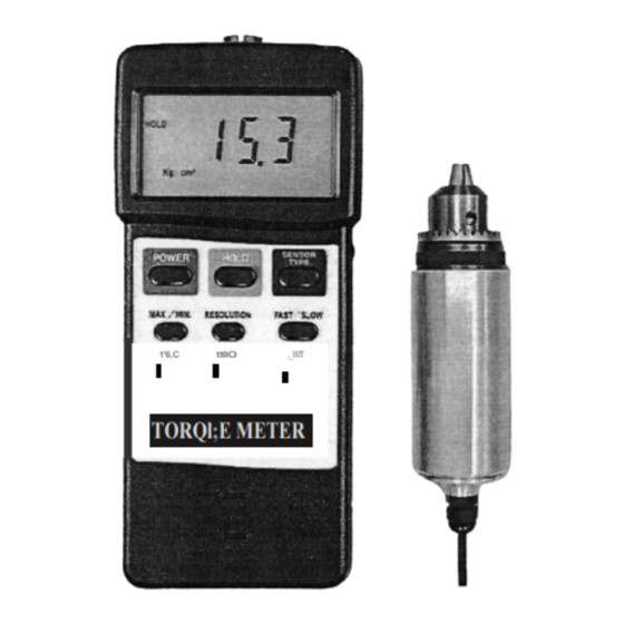
15 Kg-cm
TORQUE METER
Your purchase
of this
T O R Q U E
M E T E R
TACHOMETER marks a
step forward for you into
the
field
of
precision
measurement.
Although
this TORQUE METETR is a
complex
and
delicate
instrument,
its
durable
structure will allow many
years of use if proper
-
-
-
operating techniques are
developed. Please read
,_HfT
1'6,C
ttllO
the following instructions
carefully and always keep
TORQl;E METER
this manual within easy
reach.
OPERATION MAN UAL
Advertisement
Table of Contents

Subscribe to Our Youtube Channel
Related Manuals for PCE Health and Fitness 15 Kg-cm


Summary of Contents for PCE Health and Fitness 15 Kg-cm
- Page 1 15 Kg-cm TORQUE METER Your purchase of this T O R Q U E M E T E R TACHOMETER marks a step forward for you into field precision measurement. Although this TORQUE METETR is a complex delicate instrument, durable...
- Page 2 TABLE OF CONTENTS 1. FEATURES ............1 2. SPECIFICATIONS ............1 2-1 General Specifications ........... 2 2-2 Display Unit/Max. range/Resolution ..... 3 3. FRONT PANEL DESCRIPTION ........4 3-1 Display ..............4 3-2 Power Button ............4 3-3 Hold Button ............4 3-4 "...
-
Page 3: Specifications
1. FEATURES Professional torque meter with 15 Kgf-cm torque probe, full set. 3 kind display unit select button of Kgf -cm, LBf -inch and Newton -cm on the front panel. Data hold button to freeze the desired reading. Peak measu rement to hold the peak value. Selecting the high resolution or low resolution. - Page 4 Accuracy ± ( 1.5 % 5 d ) Resolution High resolution 0.01 Kgf-cm 0.01 LBf-inch 0.1 N-cm Newton Low resolution 0.1 Kgf-cm 0.1 LBf-inch 1 N-cm Newton Exclusive torque sensor. Sensor Exclusive microcomputer circuit. Circuit Data hold Freeze the desired readinq. To hold the peak value.
- Page 5 Meter : Dimension 180 x 72 x 32 mm ( 7.1 x 2.8 x1.3 inch ) Torqueprobe: Round 48 mm Dia. x 160 mm. Accessories * Instruction manual....1 PC. included * 15 Kg torque probe....1 PC. * Pinion........1 PC. * Carrying Case......1 PC.
-
Page 6: Front Panel Description
3. FRONT PANEL DESCRIPTION 3-1 8 3-17 3-12 3-16 +---- , -l---l+- 3-15 --H-sc --H----' --+t---L- ---+if-----' 3-10 --t-+---c_J --H- Fig. 3-1 Display 3-11 Battery Compartment 3-2 Power Button /Cover 3-3 Hold Button 3-12 Sensor Input Socket Max./Min. Button 3-13 RS-232 Output Unit Button Terminal Peak Button... -
Page 7: Measuring Procedure
4. MEASURING PROCEDURE 1) Plug in the " Sensor Cable Plug " ( 3-14, Fig. 1) to meter's " Sensor Input Socket 3-12, Fig. Power the meter by push the Power Button 3-2, Fig. 1 ). 3) Push the " Sensor Type Button 3-8, Fig 1) to check if the meter's sensor type is same as the... - Page 8 7) To connect the " Cramp " ( 3-17, Fig. 1 ) to the measured installation and use the " Opinion " ( 3-18, Fig. 1) to lock " Gear " ( 3-16, Fig. 1). Ref. Fig. 2 & Fig. 3. Fig.
- Page 9 8) Zero Button Before the measurement, if the meter not show zero value, it can push the Zero Button 3-9, Fig. 1) to 11 ( tare the display value, the LCD will change to zero value. 9) Apply the torque force, the LCD will show the measured torque value.
- Page 10 (b) Push t he Max./Min But ton again, the " Min symbol along with the minimum value will appear on the display. exit the memory record function, push the Max./Min. button continuously at least 2 seconds. The display will revert to the current reading.
-
Page 11: Auto Power Disable
Power management AUTO POWER MANUAL POWER OFF (Not activated during Memory Record Selection) 5. AUTO POWER DISABLE The instrument has built -in Auto Power Shut-off order to prolong battery life. The meter will switch automatically if none the buttons are pressed within approx. - Page 12 Center Pin .........Pin 2 Ground/shield ........Pin 5 The 16 digit data stream will be displayed in the following format Each digit indicate the following status : End Word D1 & D8 Display reading, D1 = LSD, D8 = MSD For example /f the display reading is 1234, then DB to 01 is : 00001234...
-
Page 13: Battery Replacement
7. BATTERY REPLACEMENT 1) When the left corner of LCD display show " ", It is necessary to replace the battery. However, within specification measurement may still be made several hours after low battery indicator appears before the instrument become inaccurate.
Need help?
Do you have a question about the 15 Kg-cm and is the answer not in the manual?
Questions and answers