Table of Contents
Advertisement
Quick Links
Advertisement
Table of Contents

Related Manuals for Ross openGear ADC-8434-A


Summary of Contents for Ross openGear ADC-8434-A
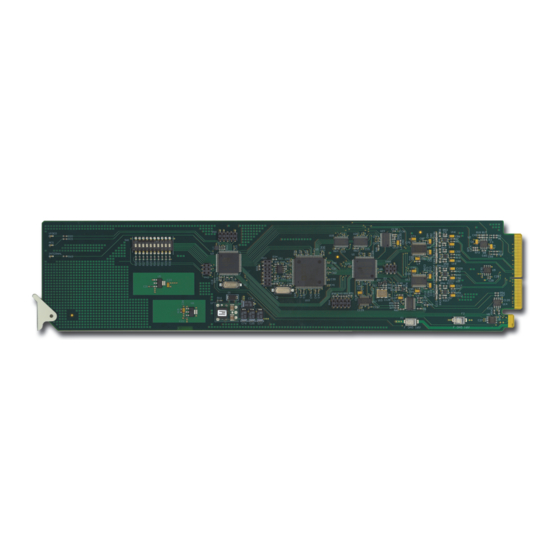
- Page 1 ADC-8434-A Quad Analog Audio to AES Converter User Manual...
- Page 2 Ross has become well known for the Ross Video Code of Ethics. It guides our interactions and empowers our employees. I hope you enjoy reading it below. If anything at all with your Ross experience does not live up to your expectations be sure to reach out to us at solutions@rossvideo.com.
- Page 3 Ross Video. While every precaution has been taken in the preparation of this document, Ross Video assumes no responsibility for errors or omissions. Neither is any liability assumed for damages resulting from the use of the information contained herein.
- Page 4 Operation of this equipment in a residential area is likely to cause harmful interference in which case the user will be required to correct the interference at his own expense. Notice — Changes or modifications to this equipment not expressly approved by Ross Video Ltd. could void the user’s authority to operate this equipment. Canada This Class “A”...
- Page 5 To avoid the potential release of those substances into the environment and to diminish the need for the extraction of natural resources, Ross Video encourages you to use the appropriate take-back systems. These systems will reuse or recycle most of the materials from your end-of-life equipment in an environmentally friendly and health conscious manner.
-
Page 7: Table Of Contents
Contents Introduction Overview..........................1-2 Features........................1-2 Functional Block Diagram....................1-3 User Interfaces ........................1-4 DashBoard Control System ................... 1-4 Card-edge Controls....................1-4 Documentation Terms and Conventions................1-5 Installation Before You Begin ........................ 2-2 Static Discharge..................... 2-2 Unpacking......................2-2 Installing the ADC-8434-A ....................2-3 Rear Modules for the ADC-8434-A .............. - Page 8 ii • Contents ADC-8434-A User Manual (Iss. 02)
-
Page 9: Introduction
Documentation Terms and Conventions A Word of Thanks Congratulations on choosing an openGear ADC-8434-A Quad Analog Audio to AES Converter. Thank you for joining the group of worldwide satisfied Ross Video customers! Should you have a question pertaining to the installation or operation of your ADC-8434-A, please contact us at the numbers listed on the back cover of this manual. -
Page 10: Overview
Overview The ADC-8434-A Quad Analog Audio to AES Converter is a broadcast quality, modular product used to convert four analog audio channels to two, 24bit, unbalanced AES-3id signals. The ADC-8434-A accepts four analog audio signals (two stereo pairs) and provides two copies of each of the two AES / EBU output signals. -
Page 11: Functional Block Diagram
Functional Block Diagram This section provides a functional block diagram that outlines the workflow of the ADC-8434-A. Figure 1.1 Simplified Block Diagram — 8310AR-036 and 8320AR-036 Full Rear Modules ADC-8434-A User Manual (Iss. 02) Introduction • 1–3... -
Page 12: User Interfaces
User Interfaces The ADC-8434-A offers the following interfaces for control and monitoring. DashBoard Control System DashBoard enables you to monitor and control openGear frames and cards from a computer. DashBoard communicates with other cards in the openGear frame through the Network Controller Card. -
Page 13: Documentation Terms And Conventions
Documentation Terms and Conventions The following terms and conventions are used throughout this manual. Terms The following terms are used: • “Board”, and “Card” refer to openGear terminal devices within openGear frames, including all components and switches. • “DashBoard” refers to the DashBoard Control System. •... - Page 14 1–6 • Introduction ADC-8434-A User Manual (Iss. 02)
-
Page 15: Installation
Installation In This Chapter This chapter provides instructions for installing the Rear Module(s) for the ADC-8434-A, installing the card into the frame, and cabling details. The following topics are discussed: • Before You Begin • Installing the ADC-8434-A • Cabling for the ADC-8434-A •... -
Page 16: Before You Begin
Unpacking Unpack each ADC-8434-A you received from the shipping container and ensure that all items are included. If any items are missing or damaged, contact your sales representative or Ross Video directly. 2–2 • Installation... -
Page 17: Installing The Adc-8434-A
Installing the ADC-8434-A This section outlines how to install a Rear Module in an openGear frame. The same procedure applies regardless of the frame or card type. However, the specific Rear Module you need to install depends on the frame you are using. Note that Slot 1 is the left most slot as you look into the openGear frame from the front. -
Page 18: Installing The Adc-8434-A
5. Using a Phillips screwdriver and the supplied screw, fasten the Rear Module to the back plane of the frame. Do not over tighten. 6. Ensure proper frame cooling and ventilation by having all rear frame slots covered with Rear Modules or Blank Plates. Installing the ADC-8434-A Use the following procedure to install the ADC-8434-A in an openGear frame: 1. -
Page 19: Cabling For The Adc-8434-A
Cabling for the ADC-8434-A This section provides information for connecting cables to the installed Rear Modules on the openGear frames. Connect the input and output cables according to the following sections. DFR-8310 Series Frame Cabling In the DFR-8310 series frames, the ADC-8434-A is used with the 8310AR-036 Rear Module. Each module occupies one slot and accommodates one card. -
Page 20: Software Upgrades For The Adc-8434-A
— DashBoard version 3.0.0 or higher is required for this procedure. To upgrade the software on a card 1. Contact Ross Technical Support for the latest software version file. 2. Display the Device View of the card by double-clicking its status indicator in the Basic Tree View. -
Page 21: User Controls
User Controls In This Chapter This chapter provides a general overview of the user controls available on the ADC-8434-A. The following topics are discussed: • Card Overview • Configuring the DIP Switches • Control and Monitoring Features ADC-8434-A User Manual (Iss. 02) User Controls •... -
Page 22: Card Overview
OFF — DIP Switch status is reported in DashBoard, however DIP Switch settings are ignored. Parameter adjustments made in DashBoard are applied. SW3 is used for factory service only. Do not use SW3 unless instructed to do so by Ross Technical Support personnel. - Page 23 SW7, SW8 — Output Mode Selection 2 SW7 and SW8 are used in conjunction to set the output mode of the second audio converter. Refer to the section “Setting the Output Modes” on page 3-4 for details. SW9, SW10 — Input Level Selection SW9 and SW10 are used in conjunction to specify the input level (+4dB).
-
Page 24: Configuring The Dip Switches
Configuring the DIP Switches This section provides a brief summary of the DIP switches of the ADC-8434-A. Refer to Figure 3.1 for DIP Switch locations. Figure 3.2 shows all the DIP Switches in the OFF position. Figure 3.2 Jumper and Switch Locations Enabling Card-edge Control Ensure that SW1 is set to ON and SW2 is set to ON if you are going to use the card-edge DIP Switches to change settings on the card. -
Page 25: Control And Monitoring Features
Control and Monitoring Features This section provides information on the LEDs for the ADC-8434-A. Refer to Figure 3.3 for the location of the LEDs. Figure 3.3 ADC-8434-A Card-edge Controls Status LEDs on the ADC-8434-A The front-edge of the ADC-8434-A has LED indicators for the communication activity. Basic LED displays and descriptions are provided in Table 3.4. - Page 26 3–6 • User Controls ADC-8434-A User Manual (Iss. 02)
-
Page 27: Dashboard Menus
DashBoard Menus In This Chapter This chapter provides a summary of the menus available for the ADC-8434-A. Parameters noted with an asterisk (*) are the default values. The following topics are discussed: • Status Tabs • Settings Tab Operating Tip —... -
Page 28: Status Tabs
Item Parameters Description Card Name Quad Analog Audio to AES Converter Product ADC-8434-A Supplier Ross Video Ltd. Card Info Serial Number Indicates the serial number of the board Software Rev ##.## Indicates the software version Card Status Tab Table 4.2 summarizes the read-only information displayed in the Card Status tab. -
Page 29: Settings Tab
Settings Tab Table 4.3 summarizes the Settings options available in DashBoard. Table 4.3 Settings Menu Items Tab Title Item Parameters Description External reference connected to Frame 1 Frame Ref 1 and selected External reference connected to Frame 2 Reference Frame Ref 2 and selected Uses the internally generated 48kHz Internal... - Page 30 4–4 • DashBoard Menus ADC-8434-A User Manual (Iss. 02)
-
Page 31: Specifications
Specifications In This Chapter This chapter provides the technical specifications for the ADC-8434-A. Note that specifications are subject to change without notice. The following topics are discussed: • Technical Specifications ADC-8434-A User Manual (Iss. 02) Specifications • 5–1... -
Page 32: Technical Specifications
Technical Specifications This section provides the technical specifications for the ADC-8434-A. Table 5.1 ADC-8434-A Technical Specifications Category Parameter Specification Number of Inputs 4 balanced channels (2 stereo pairs) Connector Terminal Block (WECO™) Analog Inputs Impedance >20kOhms Nominal Input Level +4dB Signal (from DFR-8300 series AES-3id, DARS, Video Black frame) -
Page 33: Service Information
Service Information In This Chapter This chapter contains the following sections: • Troubleshooting Checklist • Warranty and Repair Policy ADC-8434-A User Manual (Iss. 02) Service Information • 6–1... -
Page 34: Troubleshooting Checklist
Troubleshooting Checklist Routine maintenance to this openGear product is not required. In the event of problems with your ADC-8434-A, the following basic troubleshooting checklist may help identify the source of the problem. If the frame still does not appear to be working properly after checking all possible causes, please contact your openGear products distributor, or the Technical Support department at the numbers listed under the “Contact Us”... -
Page 35: Warranty And Repair Policy
ADC-8434-A. If required, a temporary replacement frame will be made available at a nominal charge. Any shipping costs incurred will be the responsibility of you, the customer. All products shipped to you from Ross Video Limited will be shipped collect. - Page 36 Contact Us Contact our friendly and professional support representatives for the following: • Name and address of your local dealer • Product information and pricing • Technical support • Upcoming trade show information Telephone: +1 613 • 652 • 4886 Technical After Hours Emergency: +1 613 •...
Need help?
Do you have a question about the openGear ADC-8434-A and is the answer not in the manual?
Questions and answers