
Related Manuals for RadonAway AIRaider 433-S50

Summary of Contents for RadonAway AIRaider 433-S50
- Page 1 AIRaider ™ Instruction & Installation Manual All Residential & Small System Models IN063 Rev.D 0120 3 Saber Way, Ward Hill, MA 01835 | radonaway.com...
- Page 2 Figure 4 - Plumbing Installation (433-S50).............................9 Figure 5 - Plumbing Installation (433-S50X)............................10 Figure 6 - Wiring Diagram 433 115V/230V............................12 Figure 7 - Wiring Diagram 433 S50/115V..............................13 Figure 8 - Wiring Diagram S50X/115V..............................14 Figure 9 - Wiring Diagram 321/115V..............................15 Figure 10 - Vent Line Connection................................16 Figure 11 - Vent Line Installation (2 inch)............................16 Figure 12 - Vent Line Installation (3 inch)............................16 Figure 13 - Air Filter....................................17 Figure 14 - Air Intake Connection.................................17 Figure 15 - Installed AIRaider (433-S50)............................18 IN063 Rev.D 0120 Page 2 of 22 3 Saber Way, Ward Hill, MA 01835 | radonaway.com...
-
Page 3: Pre-Installation
The AIRaider Systems are diffused bubble aeration systems for the removal of radon and other VOC’s from residential and municipal water supplies. This installation/operation manual is designed to guide professionals through the safe and proper installation of the AIRaider Systems. Before beginning the installation of the AIRaider System, there are 5 items to be considered. They are: 1. Safety 2. Installation Site Requirements 3. Inspection of System Components 4. Necessity for Qualified Technicians 5. Knowledge of all Contaminants in the Water 1.1. Safety Matters Safety is the most important step in the installation process. Never perform any step of the installation that you are not qualified to perform (i.e. Electrical or plumbing hook up). It is important that you read through the entire manual prior to beginning the installation. When performing the installation, work slowly and deliberately. Follow all instructions carefully and never take shortcuts. Our team of technicians is available to answer your questions at 800-355-0901. WORK SAFELY! IN063 Rev.D 0120 Page 3 of 22 3 Saber Way, Ward Hill, MA 01835 | radonaway.com... -
Page 4: Water Flow Requirements
3. After 15 minutes, check the pressure gauge on the well system. Adjust the drain valve (open or close) as needed to maintain the required running system pressure (constant pressure on gauge) with the well pump running continuously. 4. Run for 5 minutes while ensuring that the pressure is not fluctuating. 5. Run water from the hose into a five gallon bucket. Using a stop watch, time how many seconds it takes to fill the bucket (Z sec.). 6. Determine the GPM by dividing 60 seconds by the number of seconds it took to fill the bucket GPM = ( 60 / Z ) x 5 (Z sec.). Multiply the answer by 5 gallons. This gives you the GPM. 7. Repeat steps 5 and 6 and average the 2 numbers. The answer is the well pump output in gallons per minute. It is recommended that this number be indelibly recorded in an obvious location, together with the date of test, as it will be required when setting the AIRaider System and may be required for future troubleshooting of the well pump system or the AIRaider System. IN063 Rev.D 0120 Page 4 of 22 3 Saber Way, Ward Hill, MA 01835 | radonaway.com... - Page 5 FAILURE TO REMOVE OTHER CONTAMINANTS INCLUDING SEDIMENT CAN REDUCE SYSTEM EFFECTIVENESS AND MAY RESULT IN SYSTEM DAMAGE , COMPONENT MALFUNCTION, PROPERTY DAMAGE, AND PERSONAL INJURY. IN063 Rev.D 0120 Page 5 of 22 3 Saber Way, Ward Hill, MA 01835 | radonaway.com...
-
Page 6: Installation Instructions
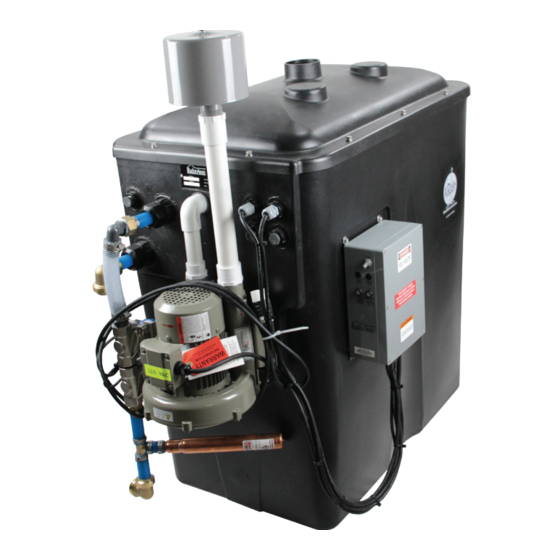
SAFETY TIP: Do Not undertake any step for which you are Not Qualified. 433-S50 433 & 433-1 Figure 1 a,b,c Typical System (Repressurization Systems not shown, sold separately on 321, 433 and 433-1) IN063 Rev.D 0120 Page 6 of 22 3 Saber Way, Ward Hill, MA 01835 | radonaway.com... -
Page 7: System Location
2. Install the Suction Check Valve provided with the Grundfos MQ3 Pump into the pump inlet as shown in the pump installation instructions. This will prevent loss of pump prime and possible interruptions in the water supply to the house. Remove the priming plug from the pump and add the specified volume (See Pump Installation Instructions) of water to the pump. Either re-install the priming plug or install a ⅜” NPT Figure 2 x 2” long pipe nipple and attach a ¼” NPT Pressure Gauge Pump & Bypass Assembly with with ¼” x ⅜” FNPT Reducer to the pipe nipple (Fig. 2). IN063 Rev.D 0120 Page 7 of 22 3 Saber Way, Ward Hill, MA 01835 | radonaway.com... - Page 8 3. Sit the pump onto the mounting bracket and connect pump inlet to system outlet. The system outlet is provided with a ¾” Sharkbite Connection suitable for ¾” Nominal Copper Tube or Pex Tube; insertion length into Sharkbite Fitting is 1”. Additional fittings will be required to connect the tube to the 1” MNPT threaded connection on the MQ3-45 Pump. Fittings required may vary with pump used. Cut the tubing to the length required to align the pump base with the mounting holes in the pump mounting bracket. Bolt the pump to the mounting bracket. 4. With the System located as desired, install the pipe/tube from the pump discharge to the desired location of supply to house. At the house end a tee is required to accommodate supply to house and to System Bypass Connection. Fittings will be required to connect to the 1” MNPT threaded connection on the MQ3-45 Pump. Fittings required may vary with pump used. The optional Bladder Tank has a ¾” MNPT threaded connection. A tee will be required if the bladder tank is installed, otherwise an elbow may be used at the same location. To facilitate removal of pump for service, a quick disconnect (sharkbite as illustrated, or pipe union) is recommended on the pump side of the required System Outlet Valve (normally open ball valve). Figure 3 Installed 433 ND System 5. Install pipe/tube from System inlet (Fig. 2) to the desired location of the supply from the well tank. At the supply end a tee is required to accommodate supply from the well and the system bypass connection. The system inlet is provided with a ¾” Sharkbite Elbow suitable for ¾” Nominal Copper Tube or Pex Tube, insertion length into Sharkbite Fitting is 1”. A System Inlet Valve (normally open ball valve) is required between the tee and Sharkbite Elbow. 6. Install the pipe/tube between the tees at the desired locations of the supply to house and the supply from well. A System Bypass Valve (Normally Closed Ball Valve) is required between the tees. IN063 Rev.D 0120 Page 8 of 22 3 Saber Way, Ward Hill, MA 01835 | radonaway.com...
- Page 9 WARNING: Bladder Tank must be supported by hanger attached to wall or joist. Figure 4 Plumbing Installation 433S ND System 6. Making sure the Bypass valve is open and Inlet and Outlet Valves are closed, slowly open the water main valve and check for leaks. 7. Slowly change bypass to the “service” configuration, Bypass valve closed, inlet and outlet valves open. Prime jet pump as per Manufacturers Instructions (See enclosed Jet Pump Manual) if not previously primed. Note that integral pump on 433-S75 and 433-S50 systems will self prime when the system tank is filled. IN063 Rev.D 0120 Page 9 of 22 3 Saber Way, Ward Hill, MA 01835 | radonaway.com...
- Page 10 INSTALLATION INSTRUCTIONS Figure 5 Plumbing Installation 433-S50X IN063 Rev.D 0120 Page 10 of 22 3 Saber Way, Ward Hill, MA 01835 | radonaway.com...
-
Page 11: Electrical Hook-Up
6. Connect the power line to the control panel as shown in the applicable wiring diagram (See Figures 6, 7, 8, 9 - on pages 12-15). 7. Connect power line to power source *. The required Voltage is either 120V or 240V and is indicated by an “X” marked in the check box next to either the 120V or 240V marking on the nameplate. Follow all code requirements regarding wire and circuit breaker size. * Manufacturer recommends that the AIRaider System be directly wired to the panel on a dedicated circuit. IN063 Rev.D 0120 Page 11 of 22 3 Saber Way, Ward Hill, MA 01835 | radonaway.com... - Page 12 INSTALLATION INSTRUCTIONS 321ND and 433ND 115V - 1Ph-60Hz Power Supply Figure 6 AIRaider 321ND and 433ND Wiring Diagram 115V IN063 Rev.D 0120 Page 12 of 22 3 Saber Way, Ward Hill, MA 01835 | radonaway.com...
- Page 13 INSTALLATION INSTRUCTIONS 433-S50(X)ND and 321-S50X with ½HP Submersible Pump 115V-1PH-60Hz Power Supply Figure 7 AIRaider 433-S50(X)ND and 321-S50X Wiring Diagram 115V IN063 Rev.D 0120 Page 13 of 22 3 Saber Way, Ward Hill, MA 01835 | radonaway.com...
-
Page 14: Vent Line Installation
90° Bend = 15 Equiv. Linear Ft ; 45° Bend = 7 Equiv. Linear Ft. Figure 12 n (3 inch) IN063 Rev.D 0120 Page 14 of 22 3 Saber Way, Ward Hill, MA 01835 | radonaway.com... - Page 15 Figure 12 Note: In-Line Air Filters are also available from the Manufacturer. Air Intake Connection IN063 Rev.D 0120 Page 15 of 22 3 Saber Way, Ward Hill, MA 01835 | radonaway.com...
-
Page 16: System Start-Up
Note: Priming process for the jet pump and pressure settings may vary with repressurization system. IN063 Rev.D 0120 Page 16 of 22 3 Saber Way, Ward Hill, MA 01835 | radonaway.com... -
Page 17: System Check
Release the lower float. d.While the tank is still filling lift the upper float; water in flow should stop and the blower will remain running. Release the upper float. Pushing down the lower float on 433-S50 and 433-S50X Systems will shut off the pump. e. Remember to shut off any open taps within the residence. 4. Replace the lid and secure with the fasteners provided. With the System running check the lid for air leaks between lid gasket and tank. If leaks occur the fasteners should be tightened until leaks are eliminated. 5. Make sure you have properly labeled the system with the necessary installer information (i.e. company name, phone #, date installed, etc.) and you have left all system information with the home owner. 6. The AIRaider System is now operational. Recommended Installation Options: Overflow Protection and Alarm 1. It is recommended that a Flood Stop (P/N 28276) be installed prior to use of this system to provide point of leak detection, whereby a motorized ball valve will automatically shut off the system and prevent potential overflows should debris clog a shut-off valve. 2. It is recommended that a basement Water Alarm be installed to warn residents of water tank overflows or system leaks. IN063 Rev.D 0120 Page 17 of 22 3 Saber Way, Ward Hill, MA 01835 | radonaway.com... - Page 18 • Check and clean inlet screen on pump. • Using a wet/dry vac, clean sediment from bottom of aeration tank if necessary. • Clean (if necessary) tank and diffusers of all mineral buildup. • Chlorinate tank and lines by pouring ¼ cup of chlorine into the first aeration chamber. • Check all control panel connections and electrical components (blower, pump, timer, fuses, etc.) for proper operation. • Check float switches for proper operation. • Inspect vent line for possible obstructions. • Run system through two cycles to ensure good working order. IN063 Rev.D 0120 Page 18 of 22 3 Saber Way, Ward Hill, MA 01835 | radonaway.com...
-
Page 19: Maintenance
• Using a wet/dry vac, clean sediment from bottom of aeration tank if necessary. • Clean (if necessary) tank and diffusers of all mineral build up. • Chlorinate tank and lines by pouring ¼ cup of chlorine into the first aeration chamber. • Check all control panel connections and electrical components (blower, pump, timer, fuses, etc.) for proper operation. • Check float switches for proper operation. • Inspect vent line for possible obstructions. • Run system through two cycles to ensure good working order. • Perform Water Test. 4.3 Recommended Additional Service* • Every 3 years, replace all hoses. • Every 3-5 years, replace the solenoid valves. * During Annual Service IN063 Rev.D 0120 Page 19 of 22 3 Saber Way, Ward Hill, MA 01835 | radonaway.com... -
Page 20: 2 3 4 5 Trouble Shooting
• Check bladder tank. • Replace jet pump and/or bladder tank as necessary. • Clear sediment strainers on faucets. Low water flow at faucets • Clear pump inlet screen/water injector. • Replace pump if necessary. Loud banging when solenoids shut • Install water hammer suppressor or loop of flexible hose in pump inlet line. • Shorten the length of pipe between the well pressure tank and the system. Solenoids chatter when closing • Check On/Off float for proper operation. Replace if necessary. • Check fuses in control panel. Blower not running • Replace timer if necessary. • Replace blower if necessary. • Check On/Off float for proper operation. Blower does not stop running • Check Timer Settings. • Replace Timer Relay if necessary. Pump is short cycling • Bladder tank may be ruptured. Replace if necessary. • Check pressure switch on pump for proper operation. Pump won't shut off • Call for support. IN063 Rev.D 0120 Page 20 of 22 3 Saber Way, Ward Hill, MA 01835 | radonaway.com... -
Page 21: Limited Warranty
LIMITED WARRANTY Subject to applicable consumer protection legislation, RadonAway warrants that the AIRaider will be free from defective materials and workmanship for the period of two ™ (2) years from the date of purchase. Warranty is contingent on installation and system maintenance (including annual service requirement) in accordance with the provided System Installation and Instruction manu- al. This warranty does not apply where repairs or alterations have been made or attempt- ed by others; or the unit has been abused or misused. Warranty does not include damage in shipment unless the damage is due to the negligence of RadonAway. To make a claim under these limited warranties, you must return the defective item to RadonAway. All other warranties, expressed or written are not valid. RadonAway is not responsible for installation or removal cost associated with this warranty. In no case is RadonAway liable beyond repair or replacement of the defective product FOB RadonAway. RADONAWAY SPECIFICALLY DISCLAIMS ANY WARRANTY OF FITNESS FOR A PARTICULAR PURPOSE. THERE ARE NO WARRANTIES WHICH EXTEND BEYOND THE DESCRIPTION ON THE FACE HEREOF. - Page 22 3 SaberWay Ward Hill, MA 01835 Phone: (800) 355-0901 Fax: (978) 521-3964 E-mail: sales@spruce.com...
Need help?
Do you have a question about the AIRaider 433-S50 and is the answer not in the manual?
Questions and answers