
Related Manuals for NXP Semiconductors UM11057 LPCXpresso845MAX


Summary of Contents for NXP Semiconductors UM11057 LPCXpresso845MAX
- Page 1 UM11057 LPCXpresso845MAX Rev. 1.0 — 9 June 2017 User Manual Document information Info Content Keywords LPCXpresso845MAX, OM13097, LPC845, LPC844 Abstract LPCXpresso845MAX User Manual...
-
Page 2: Contact Information
UM11057 NXP Semiconductors User Manual Revision history Date Description 20170526 First draft Contact information For more information, please visit: http://www.nxp.com For sales office addresses, please send an email to: salesaddresses@nxp.com UM11057 All information provided in this document is subject to legal disclaimers. -
Page 3: Introduction
UM11057 NXP Semiconductors User Manual 1. Introduction The LPCXpresso-MAX family of boards provides a powerful and flexible development system for NXP's low end Cortex-M0+ MCUs. They can be used with a range of development tools, including the MCUXpresso IDE toolchain. The LPCXpresso845MAX board is developed by NXP to enable evaluation of and prototyping with the LPC84x family of MCUs. -
Page 4: Board Layout
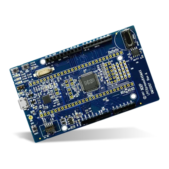
UM11057 NXP Semiconductors User Manual 2. Board Layout Figure 2 below shows the layout of the LPCXpresso845MAX board, indicating location of jumpers, buttons, connectors/expansion options and MCU devices. Fig 2. Board layout (top silkscreen) Table 1 shows the layout of the LPCXpresso845MAX board, indicating location of jumpers, buttons, connectors/expansion options and MCU devices. - Page 5 UM11057 NXP Semiconductors User Manual Table 1. Jumpers and connectors Circuit reference Description Reference section LPCXpresso expansion connector. Section 5.3 External SWD debug connector for LPC845. Section 4.1 External SWD debug connector for LPC11U35 (not installed, would be Section 4 mounted on underside of PCB.)
-
Page 6: Getting Started
UM11057 NXP Semiconductors User Manual 3. Getting Started The LPCXpresso845MAX board is pre-programmed with a simple program to blink a user LED, indicating that the target MCU is running. Connect a micro USB cable from connector J4 to a host computer or power supply to power up the board and run this program. -
Page 7: Ides
UM11057 NXP Semiconductors User Manual 3. In the “Import project(s) from file system...” dialog box that opens, click “Browse...” in the Project Archive (from zip) section, and select the LPC84x Code Bundle zip file from the Code Bundles directory in the MCUXpresso IDE installation (or select a version downloaded from nxp.com, as described in Step 1 above.) Click “Next >”... -
Page 8: Debug Probe
UM11057 NXP Semiconductors User Manual 4. Debug Probe The on-board LPC11U35 provides CMSIS-DAP debug probe functionality, plus a virtual comm port (VCOM) capability via PIO1_16 and PIO1_17 of the LPC845 target. This functionality bridges the LPC845 serial port via USB, so that PC applications such as TeraTerm and PuTTY can communicate directly with the target. -
Page 9: Expansion Connectors/Headers
UM11057 NXP Semiconductors User Manual 5. Expansion connectors/headers The LPCXpresso845MAX board provides multiple options to add additional circuitry or off the shelf expansion boards; this section describes these options. For further details please refer to the board schematics. 5.1 Arduino UNO Rev 3 expansion connectors... -
Page 10: Pmod Connector
UM11057 NXP Semiconductors User Manual Note that the default ports for ISP boot are connected to J1 (I2C) J2 (USART). The Arduino power connector (J5) pin 2 (IOREF) and pin 3 (+3V3) are routed to the 3.3V regulator output. J5 pin 5 (5V) is routed to the 5V supply from USB. J5 pin 8 (VIN) can also be connected to this 5V supply by closing solder jumper SJ16 (this connection is required by some Arduino shields). -
Page 11: Power Measurement
UM11057 NXP Semiconductors User Manual 6. Power measurement JP2 is provided to enable supply current to the LPC845 to be measured by placing an ammeter in line with JP2 pins. By default this jumper is bypassed by solder jumper (SJ6). -
Page 12: Speaker Driver
UM11057 NXP Semiconductors User Manual 7.4 Speaker driver The LPC845 DACOUT output PIO0_29 is route to an IS31AP4991 speaker driver (see Integrated Silicon Solutions web site for datasheet). This device can drive 8 to 32 ohm speakers; a 32 ohm speaker is supplied with the board and resistors have been selected to provide a reasonable volume level for musical tones. -
Page 13: Legal Information
In no event shall NXP Semiconductors be liable for any indirect, incidental, punitive, special or consequential damages (including - without limitation - lost NXP Semiconductors does not accept any liability related to any default,... -
Page 14: Table Of Contents
UM11057 NXP Semiconductors User Manual 9. Contents Introduction ......3 Board Layout ......4 Getting Started .
Need help?
Do you have a question about the UM11057 LPCXpresso845MAX and is the answer not in the manual?
Questions and answers