
Subscribe to Our Youtube Channel
Related Manuals for NXP Semiconductors LPCXpresso804


Summary of Contents for NXP Semiconductors LPCXpresso804
- Page 1 LPCXpresso804 User Manual for LPCXpresso804 Board Rev. 1.1 — 24 September 2018 User Manual Document information Info Content Keywords LPCXpresso804, OM40001, LPC804 Abstract LPCXpresso804 User Manual...
- Page 2 LPCXpresso804 NXP Semiconductors User Manual Revision history Date Description 20180209 First release 20182409 Corrected section 8.2 text (PLU output) Contact information For more information, please visit: http://www.nxp.com For sales office addresses, please send an email to: salesaddresses@nxp.com UM11083 All information provided in this document is subject to legal disclaimers.
-
Page 3: Introduction
The LPCXpresso family of boards provides a powerful and flexible development system for NXP's Cortex-M MCUs. They can be used with a range of development tools, including the MCUXpresso IDE. The LPCXpresso804 board is developed by NXP to enable evaluation of and prototyping with the LPC804 MCU. -
Page 4: Board Layout
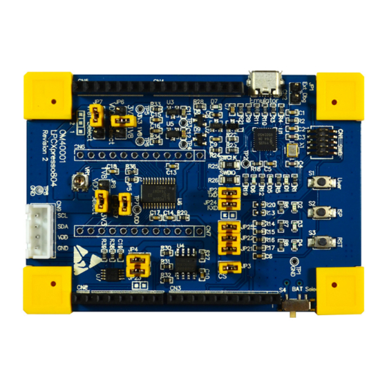
LPCXpresso804 NXP Semiconductors User Manual • C Grove connector for easy connection of sensors, or to use the LPCXpresso804 as an I/O expander peripheral 2. Board Layout Figure 2 below shows the layout of the LPCXpresso804 board, indicating location of jumpers, buttons and connectors/expansion options. - Page 5 LPCXpresso804 NXP Semiconductors User Manual Table 1. Jumpers and connectors (LPCXpresso804 board) Circuit reference Description Reference section Install an ammeter across JP5 to measure current supplied to the LPC804 device. JP5 should be installed at all other times. This jumper is not installed by default. It is provided for future support of See schematic.
-
Page 6: Getting Started
3.1 Initial setup and pre-programmed demo program The LPCXpresso804 board is pre-programmed with a diagnostic demo program, which tests various features of the board. This program utilizes the UART LPC804 output, which is connected to the debug probe, which acts a serial to USB bridge to a host computer (as well as providing the CMSIS-DAP debug interface.) To ensure a correct operation, a... -
Page 7: Using Lpcxpresso804 With 3Rd Party Ides
7. Ensuring the LPCXpresso804 is connected to the host computer, click Debug in the Quickstart panel. The IDE will search for available debug probes. Select the debug probe that appears for your board, then click OK. -
Page 8: Debugger Firmware Update (Optional)
An external debug probe that supports ARM’s SWD interface, such as a SEGGER J-Link or PE Micro probe, can be used with the LPCXpresso804 board. The external probe must be connected to header CN1. When an external debug probe is used, the on-board probe must be held in reset by placing a jumper on JP1. -
Page 9: Arduino Uno Rev 3 Expansion Connectors
Note that the default ports for ISP UART boot are connected to CN2. 5.2 Grove connector The LPCXpresso804 board includes a header for connection of Seeed Studio Grove I sensors. This header supplies the I C connections plus 3.3V and ground. -
Page 10: Power Supplies And Supply Current Measurement
LPCXpresso804 NXP Semiconductors User Manual 6. Power supplies and supply current measurement This section describes available power options for the board, and how current consumption of the LPC804 can be measured. 6.1 Board powering options The Board may be powered by the USB connector (CN2), via the Arduino connector (5V input pin) or by a coin cell battery inserted into the holder on the underside of the board. -
Page 11: Temperature Sensor (Lm75, Circuit Ref U7)
7.5 SPI flash (Winbond W25X10CLSNIG, circuit ref U4) A 1Mb SPI flash from Winbond is included on the LPCXpresso804. This device interfaces to the SPI peripheral of the LPC804. A jumper (JP3) is provided to this device can be disconnected (by disabling the SPI chip select PIO_16). -
Page 12: Plu Input Options
LPCXpresso804 NXP Semiconductors User Manual Table 7. PLU input on/off switches Switch LPC804 signal Notes PIO0_0 Also connected to debug UART. Remove JP2 to avoid conflicts PIO0_10 Shared with potentiometer. Move potentiometer to center position to avoid conflicts. PIO0_11 Also connected to user LED; remove JP21 to disconnect LED PIO0_4 Also connected to debug UART. -
Page 13: Capacitive Touch Shield
Table 10. Note that PI00_8 and PIO0_9 are also connected to the SPI flash data inputs/outputs, so it is advisable to remove JP3 on the LPCXpresso804 board (to disable the SPI flash memory) before installing this shield board. UM11083 All information provided in this document is subject to legal disclaimers. - Page 14 LPCXpresso804 NXP Semiconductors User Manual Table 10. Capacitive touch LED signals LPC804 I/O PIO0_20 PIO0_18 PIO0_15 PIO0_8 PIO0_9 The LPC804 Code Bundle, available under the Software and Tools tab of the OM40001 board web page (http://www.nxp.com/demoboard/OM40001), includes driver and example code to show how to use the capacitive touch feature of the board.
-
Page 15: Legal Information
It is customer’s sole responsibility to determine whether the NXP In no event shall NXP Semiconductors be liable for any indirect, incidental, Semiconductors product is suitable and fit for the customer’s applications and... -
Page 16: Table Of Contents
Initial setup and pre-programmed demo program 6 Using the board with MCUXpresso IDE ..6 Using LPCXpresso804 with 3rd Party IDEs . . . 7 Debugger firmware update (optional) ..8 Debug Probe .
Need help?
Do you have a question about the LPCXpresso804 and is the answer not in the manual?
Questions and answers