
Related Manuals for NXP Semiconductors LPCXpresso55S06


Summary of Contents for NXP Semiconductors LPCXpresso55S06
- Page 1 UM11505 LPCXpresso55S06 Development Boards Rev. 1.2 — 19 February 2021 User manual Document information Info Content Keywords LPC55S06, LPC55S0x, LPCXpresso55S06, LPC55S06-EVK Abstract LPCXpresso55S06 development board user manual...
- Page 2 UM11505 NXP Semiconductors LPCXpresso55S06 Development Boards Revision history Date Description 20210219 Corrected Typo in Section 10 “Errata”, Changed A2 to A1 20210217 Information added in Section 10 “Errata” 20201005 Initial internal release. Contact information For more information, please visit: http://www.nxp.com For sales office addresses, please send an email to: salesaddresses@nxp.com...
-
Page 3: Introduction
NXP's LPC Cortex®-M family of MCUs. They can be used with a wide range of development tools, including NXP's MCUXpresso IDE, Keil uVISION and IAR Embedded Workbench. The LPCXpresso55S06 board (order code LPC55S06-EVK) is the evaluation and development platform for the LPC55S0x/LPC550x families of MCUs. -
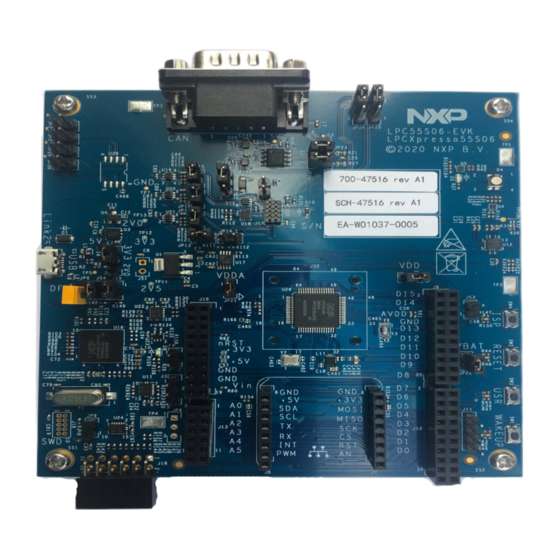
Page 4: Board Layout And Settings
UM11505 NXP Semiconductors LPCXpresso55S06 Development Boards • UART and SPI port bridging from LPC55Sxx target to USB via the onboard debug probe • Optional external debug probes with trace option (10 or 20 pin Cortex-M connectors) • External crystal oscillators •... - Page 5 UM11505 NXP Semiconductors LPCXpresso55S06 Development Boards Table 1. Indicators, buttons, connectors and LEDs Circuit Description Default Reference reference Target power indicator LED Link2 boot LED Section 4.1 RGB User LED (Tri-color Red/Green/Blue) Section 7.4 Buffer Power Selection Section 3.1, Section 4.4...
- Page 6 UM11505 NXP Semiconductors LPCXpresso55S06 Development Boards Table 1. Indicators, buttons, connectors and LEDs Circuit Description Default Reference reference Serial port header Section 6. 0.1" header providing convenient access to Flexcom 0 USART (the USART used for ISP boot). When using this port, ensure jumper JP9 is installed to disable the Link2 connection to this port and JP12 is open.
-
Page 7: Getting Started
UM11505 NXP Semiconductors LPCXpresso55S06 Development Boards Table 1. Indicators, buttons, connectors and LEDs Circuit Description Default Reference reference J7,J8 Mikroe Click site Section 8. Provides connectivity to standard Mikroe Click connectors. Shares SPI, ADC, I2C and USART connections with the J9, J10, J12, J13 expansion connectors. -
Page 8: Installation Steps For Use With Mcuxpresso Ide
UM11505 NXP Semiconductors LPCXpresso55S06 Development Boards the CMSIS-DAP protocol can be used in the default configuration. Check with your toolchain vendor for availability of specific device support packs for the LPC55Sxx series devices. Note that when using the MCUXpresso IDE, the on-board Link2 can also be booted in DFU mode by installing a jumper on JP6;... -
Page 9: Starting A Debug Session Using An External Debug Probe
UM11505 NXP Semiconductors LPCXpresso55S06 Development Boards be five devices (if using CMSIS-DAP protocol); four under Human Interface Devices (CMSIS-DAP, LPC-SIO, two HID Compliant Devices, and a USB Input Device) and one under Ports (LPC-LinkII Ucom.) Your board is now ready to use with your 3rd party tool. Follow the instructions for those tools for using a CMSIS-DAP probe. -
Page 10: On-Board (Link2) Debug Probe
VCOM port can be used if the board is running an application when no debugger is running. In order to correctly install and use the Link2 device on the LPCXpresso55S06 (required for any debugging purpose) for Windows host computers, install the drivers first. These drivers will automatically be installed when MCUXpresso IDE has already been installed. -
Page 11: Link2 Boot Led
LPC-LinkII UCom port. 4.4 Configuring the LPCXpresso55S16 to debug an off-board target The LPCXpresso55S06 board's Link2 Debug Probe may be used to debug an off-board target MCU. The on-board Link2 Debug Probe is capable of debugging target MCU's with a VDDIO range of 1.6V to 3.6V. -
Page 12: Measuring Lpc55Sxx Device Supply Current . 12 5.2 2.0V Operation
UM11505 NXP Semiconductors LPCXpresso55S06 Development Boards The Link2 Debug probe has a 2.5V regulator (U1) which draws power from USB connector J1 ("Debug Link") only. There are two other regulators, providing the option of 2.0V (U4) or 3.3V (U3) to the other devices on the board;... -
Page 13: Can-Fd Connector
P0_24 and P0_25) with its interrupt output connected to P1_23. The accelerometer has an I2C address of 0b0001111X. I2C software drivers are provided as part of the LPCXpresso55S06 SDK, and the example code is provided to illustrate how to read values from the accelerometer. -
Page 14: User (Sw3) And Wakeup (Sw1) Buttons
Refer to the schematic for further information. When using an Arduino shield with the Board, align the Arduino shield (SCL) with pin 1 of connector J9 on the LPCXpresso55S06 board. UM11505 All information provided in this document is subject to legal disclaimers. -
Page 15: Miscellaneous Board Features
UM11505 NXP Semiconductors LPCXpresso55S06 Development Boards Table 2. Arduino and LPCXpresso V3 expansion connections Expansion connector Port The odd number pins are compatible with Arduino Uno rev3 Digital 15:8, AREF, SDA & SCL connector. The even numbered pins are used for external access and expansion of LPC55Sxx signals not used by the Arduino Uno rev3 compatible interface. - Page 16 UM11505 NXP Semiconductors LPCXpresso55S06 Development Boards Fig 3. Prevention from over power consumption 11. Board operating conditions These boards have been designed for use in laboratory conditions (0 to 50 degrees Celsius) and should not be used for extended temperature testing. Refer to the data sheet of the LPC55xx MCU being used for full operating conditions for that device.
-
Page 17: Table Of Contents
UM11505 NXP Semiconductors LPCXpresso55S06 Development Boards 13. Contents Introduction ......3 Board layout and Settings ....4 Getting started . - Page 18 Right to make changes - NXP Semiconductors reserves the right to make changes to information published in this document, including without limitation specifications and product descriptions, at any time and without notice.
- Page 19 and service marks licensed by Power.org. M, M Mobileye and other Mobileye trademarks or logos appearing herein are trademarks of Mobileye Vision Technologies Ltd. in the United States, the EU and/or other jurisdictions. © NXP B.V. 2020-2021. All rights reserved. For more information, please visit: http://www.nxp.com For sales office addresses, please send an email to: salesaddresses@nxp.com Date of release: 19 Feb 2021...
Need help?
Do you have a question about the LPCXpresso55S06 and is the answer not in the manual?
Questions and answers