Advertisement
Table of Contents
Hinweis für Händler: Wenn Sie dieses Produkt für den Kunden installieren, übergeben Sie ihm nach der Installation bitte diese Bedienungsanleitung.
Vielen Dank, dass Sie sich für den Aerobar mit J2-Halterungssystem von Profile Design entschieden haben. Bitte lesen Sie diese Anweisungen aufmerksam, bevor Sie den Artikel
installieren. Zur Einhaltung der Garantiebestimmungen von Profile Design ist eine sachgemäße Installation erforderlich. Wenn Sie mit der Installation von Aerobars oder deren
Zubehör nicht vertraut sind, wenden Sie sich bitte an Ihren örtlichen Profile-Design-Händler; verwenden Sie dazu die „Händlersuche" unter www.profile-design.com oder rufen Sie
den Profile-Design-Kundendienst an.
Benötigte Werkzeuge und Materialien: 4-mm-Inbusschlüssel, 5-mm-Inbusschlüssel und Drehmomentschlüssel (in-lbs/Nm)
Gewinde wurden von Profile Design während der Produktion mit einer speziellen blauen Gewindesicherungsmasse vorbehandelt. Diese spezielle Masse ist an den Gewinden aller
mitgelieferten Schrauben deutlich sichtbar. Falls der Lack nicht erkennbar sein oder sich bei der regulären Wartung ablösen sollte, tragen Sie vor der Montage einen geeigneten,
blauen Schraubensicherungslack (beispielsweise von Loctite oder einem anderen Anbieter) auf.
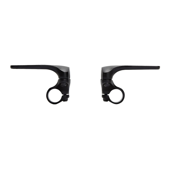
1. Entfernen Sie die M6-Schrauben von der Unterseite der Klemme.
2. Platzieren Sie die Halterung auf dem Lenker und verbinden Sie die untere U-Halterung mit der Aerobar-Halterung.
Drehen Sie die Schrauben von Hand fest.
3. Passen Sie die Breite an und neigen Sie den Lenker in die gewünschte Position. Ziehen Sie die M6-Schrauben mit
6 Nm (53 in.lbs) gleichmäßig fest.
Führen Sie Brems- und Schaltzug nicht zwischen Aerobar-Halterung und Basislenker hindurch.
WARNUNG
4. Passen Sie Drehung und Länge der Erweiterung durch Lösen der die Erweiterung sicherenden M6-Schraube an.
Sobald die gewünschte Drehung und Länge erreicht ist, ziehen Sie die M6-Schraube mit 6 Nm (53 in.lbs) fest.
5. Platzieren Sie die Armlehne in der gewünschten Position an der Halterung. Stecken Sie die M6-Schraube durch die
Armlehne und in die Halterung. Ziehen Sie die Schraube mit dem 4-mm-Inbusschlüssel sicher fest. Wiederholen Sie den
Vorgang bei der zweiten Schraube; lassen Sie sie zur Anpassung ein wenig locker.
HINWEIS: Schrauben können zur optimierten Armlehnenpositionierung nebeneinander oder von vorne
nach hinten installiert werden.
6. Drehen Sie die Armlehne in den gewünschten Winkel zur Erweiterung.
Ziehen Sie sie gleichmäßig mit 4,7 Nm (42 in.lbs) fest.
7. Drücken Sie das Polster 30 Sekunden lang fest auf die Armlehne. Wiederholen Sie den Vorgang bei der anderen Armlehne.
8. Prüfen Sie die Schrauben nach dem ersten Einsatz, später in regelmäßigen Abständen auf festen Sitz;
vergewissern Sie sich, dass sich das Aerobar-System nicht lockert.
WARNUNG
• Any failure to follow these warnings and instructions can result in breakage, slippage and or other malfunctioning of
this Profile Design component causing a loss of control of the bicycle with serious injuries. [AP1100-1-1]
• A creaking component can be a sign of potential problems. Make sure all contact surfaces between components are
clean, all bolt threads are greased or are treated with proper thread lock and tightened to Profile Design's (or the bike
manufacturers) specifications and all components are properly sized to fit together. If you continue to experience
creaking stop using the Profile Design component and call Profile Design customer service. [AP0601-2-2]
• Under tightening a bolt can result in a part coming loose while riding and an over tightened bolt can break
unexpectedly or strip the threads it is engaging while riding also resulting in a loss of control. All bolts must be
tightened to Profile Design's (or the bike manufacturer's) torque specifications. On the first and any subsequent
assembly examine all male and female threads and bolts for stripped threads, cracks and any required lubrication or
thread locking compound. [AP1100-3-2]
• Periodically, closely examine all surfaces of this Profile Design component (after cleaning) in bright sunlight to check
for any small hairline cracks or fatigue at "stress points" (such as welds, seams, holes, points of contact with other
parts etc.). If you see any cracks, no matter how small, stop using the part immediately and call Profile Design
customer service. [AP0302-4-2]
• Whenever you install any new component on your bike make sure you thoroughly try it out close to home (with your
helmet) where there are no obstacles or traffic. Make sure everything is working properly before going off on a ride or
to a race. [AP1100-5-1]
• Racing (road, mountain or multi-sport) places extreme stress on bicycles and their components (like it does riders) and
significantly shortens their usable life. If you participate in these types of events, the lifetime of the product may be
significantly shortened depending upon the level and amount of racing. The "normal wear" of a component may differ
greatly between competitive and non-competitive uses, which is why professional level riders often use new bikes and
components each season as well as having their bikes serviced by professional mechanics. Particular care should be
placed in the regular examination of your bicycle and it's components to insure your safety. [AP1100-6-1]
Profile Design gewährt auf sämtliche Produkte eine zweijährige Garantie ab Kaufdatum.
•
Detaillierte Angaben zur Profile Design-Garantie und zum Austausch bei Stürzen/Unfällen
•
finden Sie hier: www.profile-design.com/warranty
L2-Halterungssystem
Installationsanleitung
1. 、 2. 、 3.
4.
7. 、 8.
• A number of factors can reduce the life of this component to less than its warranty period. Rider size and/or strength
and riding style, high mileage, rough terrain, abuse, improper installation, sweat, adverse environmental conditions (such
as salt air or corrosive rain), travel damage (especially if bike and components are repeatedly disassembled and then
reassembled) and crashes or accidents can all contribute to the shortening of the life of this component. The more
factors that are present, the more the life of the component is reduced. [AP0801-7-2]
• Make sure the handlebar clamp area diameter matches that of the stem clamp diameter (i.e. 31.8mm, 26.0mm or
25.4mm). An incorrect match could result in handlebar and or stem damage, slippage or breakage causing a possible
loss of control and injury. [B0706-4-1]
• Carbon fiber handlebars require special attention and maintenance. For installation of a stem with carbon fiber
handlebars please refer to handlebar manufacturer's instructions prior to installation. [ST1100-1-1]
• Make sure you periodically recheck rear clamp (fork attachment) and front clamp (handlebar attachment) stem bolt
tightness (especially after riding on rough terrain) to insure a good attachment. [ST1100-2-1]
• Forks with carbon fiber steering tubes require special attention and maintenance. Refer to fork manufacturer's
instructions. [ST1100-5-1]
Note to Dealers: If you install this product for the consumer, please provide him/her with this owner's manual after installation.
Thank you for purchasing the Profile Design Aerobar Featuring the L2 Bracket System. Please read these instructions thoroughly before attempting to install this item. Proper
installation is required for compliance with the Profile Design warranty policy. If you are not familiar with installation of aerobars or their accessories, please seek the assistance of
your local Profile design dealer by logging on to www.profile-design.com and using "dealer search" or by calling the Profile Design customer service number.
Tools and materials required: 4mm Allen wrench, 5mm Allen wrench and Torque wrench (in-lbs/Nm)
Threaded areas have been pre-treated by Profile Design during production with a special blue thread locking compound. This special compound is easy to detect on the threads of
all bolts provided. If you cannot detect this thread locking compound or if you have cleaned it off through normal maintenance, re-apply a suitable blue thread locking compound as
available from Loctite or another company before assembly.
1. Remove the M6 bolts from the bottom of the clamp.
2. Place the bracket onto the bar and connect bottom U bracket to the aerobar bracket. Thread in the bolts by hand.
3. Adjust the width and tilt of the bar to desired position. Evenly tighten the M6 bolts to 6Nm (53in.lbs).
Do not route the brake or shift cables between the aerobar bracket and basebar.
WARNING
4. Adjust the rotation and length of the extension by loosening the M6 bolt securing the extension.
Once the desired rotation and length is determined tighten the M6 bolt to 6Nm (53in.lbs).
5. Place the armrest in the preferred location on the bracket. Insert the M6 bolt through the armrest and into the bracket.
Using the 4mm Allen wrench thread the bolt until it is snug. Repeat for the second bolt leaving it slightly loose to allow for
adjustment.
NOTE: Bolts can be installed side by side or front to back for optimized armrest positioning.
5.
6. Rotate the armrest to the preferred angle relative to the extension. Tighten evenly to 4.7Nm (42in.lbs).
6.
7. Press the pad onto the armrest and hold firmly for 30 seconds. Repeat for the other armrest.
8. Recheck the bolts for tightness after first usage and periodically thereafter to ensure secure
attachment of the aerobar system.
WARNING
• Any failure to follow these warnings and instructions can result in breakage, slippage and or other malfunctioning
of this Profile Design component causing a loss of control of the bicycle with serious injuries. [AP1100-1-1]
• A creaking component can be a sign of potential problems. Make sure all contact surfaces between components
are clean, all bolt threads are greased or are treated with proper thread lock and tightened to Profile Design's (or the
bike manufacturers) specifications and all components are properly sized to fit together. If you continue to experience
creaking stop using the Profile Design component and call Profile Design customer service. [AP0601-2-2]
• Under tightening a bolt can result in a part coming loose while riding and an over tightened bolt can break unexpectedly
or strip the threads it is engaging while riding also resulting in a loss of control. All bolts must be tightened to
Profile Design's (or the bike manufacturer's) torque specifications. On the first and any subsequent assembly examine
all male and female threads and bolts for stripped threads, cracks and any required lubrication or thread locking
compound. [AP1100-3-2]
• Periodically, closely examine all surfaces of this Profile Design component (after cleaning) in bright sunlight to check
for any small hairline cracks or fatigue at "stress points" (such as welds, seams, holes, points of contact with other
parts etc.). If you see any cracks, no matter how small, stop using the part immediately and call Profile Design
customer service. [AP0302-4-2]
• Whenever you install any new component on your bike make sure you thoroughly try it out close to home (with your
helmet) where there are no obstacles or traffic. Make sure everything is working properly before going off on a ride or
to a race. [AP1100-5-1]
• Racing (road, mountain or multi-sport) places extreme stress on bicycles and their components (like it does riders)
and significantly shortens their usable life. If you participate in these types of events, the lifetime of the product may be
significantly shortened depending upon the level and amount of racing. The "normal wear" of a component may differ
greatly between competitive and non-competitive uses, which is why professional level riders often use new bikes and
components each season as well as having their bikes serviced by professional mechanics. Particular care should be
placed in the regular examination of your bicycle and it's components to insure your safety. [AP1100-6-1]
Profile Design warrants all its products for two years from original purchase.
•
For further details on the Profile Design warranty and Crash Replacement policy,
•
please visit www.profile-design.com/warranty
L2 Bracket System
Installation Instructions
1. 、 2. 、 3.
4.
7. 、 8.
• A number of factors can reduce the life of this component to less than its warranty period. Rider size and/or strength
and riding style, high mileage, rough terrain, abuse, improper installation, sweat, adverse environmental conditions
(such as salt air or corrosive rain), travel damage (especially if bike and components are repeatedly disassembled and
then reassembled) and crashes or accidents can all contribute to the shortening of the life of this component. The more
factors that are present, the more the life of the component is reduced. [AP0801-7-2]
• Make sure the handlebar clamp area diameter matches that of the stem clamp diameter (i.e. 31.8mm, 26.0mm or
25.4mm). An incorrect match could result in handlebar and or stem damage, slippage or breakage causing a possible
loss of control and injury. [B0706-4-1]
• Carbon fiber handlebars require special attention and maintenance. For installation of a stem with carbon fiber
handlebars please refer to handlebar manufacturer's instructions prior to installation. [ST1100-1-1]
• Make sure you periodically recheck rear clamp (fork attachment) and front clamp (handlebar attachment) stem bolt
tightness (especially after riding on rough terrain) to insure a good attachment. [ST1100-2-1]
• Forks with carbon fiber steering tubes require special attention and maintenance. Refer to fork manufacturer's
instructions. [ST1100-5-1]
www.profile-design.com
L2 Bracket System 06/28/2016
5.
6.
Advertisement
Table of Contents

Related Manuals for Profile Design L2


Summary of Contents for Profile Design L2
- Page 1 Zur Einhaltung der Garantiebestimmungen von Profile Design ist eine sachgemäße Installation erforderlich. Wenn Sie mit der Installation von Aerobars oder deren installation is required for compliance with the Profile Design warranty policy. If you are not familiar with installation of aerobars or their accessories, please seek the assistance of Zubehör nicht vertraut sind, wenden Sie sich bitte an Ihren örtlichen Profile-Design-Händler;...
- Page 2 Herramientas y materiales necesarios: llave Allen de 4 mm, llave Allen de 5 mm y llave dinamométrica (pulg-lbs/Nm) Les zones filetées ont été pré-traitées par Profile Design pendant la production avec un composé frein-filet bleu spécial. Ce composé spécial est facile à détecter sur les filets de Las áreas roscadas han sido previamente tratadas por Profile Design durante la producción con un compuesto especial azul para sellado de roscas.
Need help?
Do you have a question about the L2 and is the answer not in the manual?
Questions and answers