Table of Contents
Advertisement
Quick Links
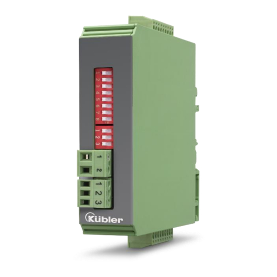
Operating Manual
Level Converter, Direction Signal Decoder and programmable pulse divider
Product features:
•
Level Converter (RS-422, HTL Single Ended, HTL Differential,
TTL and and vice-versa
•
Implementation between the two types of representations for the direction
of rotation (A/B 90 °, A/B Direction and vice versa)
•
Adjustable division ratio of directional A / B pulses
•
Adjustable division ratio for the Z pulse
•
Reset of the Z divider by external input (defined setting)
•
Zero setting of the A / B / Z divider by external input (defined Start / Stop)
•
Z divider can also be used as an independent second divider
•
Limit frequency up to 1 MHz, depending on the input format
•
Push-pull outputs direct SPS control
•
9 to 30 VDC power supply
R60076.0001
FT.1D-1D
Advertisement
Table of Contents

Related Manuals for Kübler FT.1D-1D


Summary of Contents for Kübler FT.1D-1D
- Page 1 Operating Manual R60076.0001 FT.1D-1D Level Converter, Direction Signal Decoder and programmable pulse divider Product features: • Level Converter (RS-422, HTL Single Ended, HTL Differential, TTL and and vice-versa • Implementation between the two types of representations for the direction of rotation (A/B 90 °, A/B Direction and vice versa) •...
- Page 2 FT.1D-1D_01b/CF/ Feb 2019 First revision FT.1D-1D_02a/AF/MBO/Dez 2019 FT.1D-1D extension Legal notices: All contents included in this manual are protected by the terms of use and copyrights of Fritz Kübler GmbH. Any reproduction, modification, usage or publication in other electronic and printed media as well as in the internet requires prior written authorization by Fritz Kübler GmbH.
-
Page 3: Table Of Contents
Table of Contents Safety Instructions and Responsibility ..............4 General Safety Instructions....................4 Use according to the intended purpose .................. 4 Installation ........................... 4 Cleaning, Maintenance and Service Notes ................5 Compatibility Hint ....................6 Introduction ......................7 Block diagram ...................... 7 Electrical Connections ................... -
Page 4: Safety Instructions And Responsibility
Safety Instructions and Responsibility General Safety Instructions This operation manual is a significant component of the unit and includes important rules and hints about the installation, function and usage. Non-observance can result in damage and/or impairment of the functions to the unit or the machine or even in injury to persons using the equipment! Please read the following instructions carefully before operating the device and observe all safety and warning instructions! Keep the manual for later use. -
Page 5: Cleaning, Maintenance And Service Notes
Before installation or maintenance, the unit must be disconnected from all voltage-sources. Further it must be ensured that no danger can arise by touching the disconnected voltage- sources. Devices which are supplied by AC-voltages, must be connected exclusively by switches, respectively circuit-breakers with the low voltage network. -
Page 6: Compatibility Hint
Compatibility Hint The main differences between the FT.1D-1D and the respective predecessor model are listed below: Predecessor FT.1D-1D Input RS422/DSUB clamps HTL/clamps Input characteristics RS422/HTL Single RS422/HTL Diff/HTL Single/TTL Frequency Max. 300kHz 1MHz/1MHz/350kHz/350kHz Output RS422/DSUB clamps HTL/clamps Parallel outputs Only 1 output Encoder supply 5.5V/130mA... -
Page 7: Introduction
Introduction The FT.1D-1D is a universal interface using with incremental measuring systems. The device allows the solution of the following problems: • Level conversion (RS-422, HTL single ended, HTL differential, TTL and vice versa) • Division of two-track A / B pulses with adjustable ratio 1: 1 to 1: 4096 •... -
Page 8: Electrical Connections
Electrical Connections The terminal screws should be tightened with a slotted screwdriver (blade width 2mm). DC Power Supply The device is supplied with a DC voltage between 9 ... 30 VDC via terminals 1 and 2 of X1. The current consumption depends on the level of the supply voltage and the settings and is approx. 35 mA without load from the sensor supply and additional on the extracted encoder current at the auxiliary voltage output. -
Page 9: Incremental Inputs A, /A, B, /B, Z, /Z
Incremental Inputs A, /A, B, /B, Z, /Z At terminal 2 ... 7 of X4, 3 pulse inputs are available for HTL / TTL / RS422 signals. The unused inputs must be open (HTL single ended vs. HTL differential) or terminated (unused Z track in RS- 422 or HTL differential format). -
Page 10: Control Inputs
Control Inputs Two control inputs with HTL PNP characteristics are available at terminals 2 and 3 of X2 and are used for resetting the internal dividers Unconnected control inputs are always “LOW”. All inputs are designed to receive impulses from an electronic impulse source. Notice for mechanical switching contacts: When exceptionally mechanical contacts are used, please connect an external capacitor between GND (-) and the corresponding input (+). -
Page 11: Error Ausgang
Error output An HTL error signal (input error, only with RS-422 or HTL differential) is available at the X3 screw terminal 1. (Error = low). The error is triggered by a line fault (short circuit or line break) by the input lines A, / A, B, / B or Z, / Z. -
Page 12: Input And Output Configuration
Input and output configuration Changes in the settings on the DIL switches will only be taken over by the device after the supply voltage has been switched on again! Configuration DIL1 (Front 8-pole) Function Level for HTL Single Ended: U <... -
Page 13: Level Converter A/B Pulse (A/B Divider: All Off)
Level converter A/B Pulse (A/B Divider: All OFF) If the A/B pulse have to be switched unchanged from the input to the output (no division, no change in length and position), then the DIL switch position listed below must be chosen. A level conversion is only possible if the input mode (A/B 90 °... - Page 14 Divider [A/B] DIL5 DIL6 DIL1 Comment (Left 8-pole) (Left 3-pole) (Front) Binary value division => 1 : (Binary value +1) x2 OFF OFF OFF OFF OFF OFF OFF OFF OFF OFF value 1 => 1 : 4 ON OFF OFF OFF OFF OFF OFF OFF OFF OFF value 2 =>...
-
Page 15: Setting The A/B Divider (For All Other Modes)
Setting the A/B divider (for all other modes) The division ratio for the A/B pulses is set at the DIL switches DIL5 and DIL6. The switch positions use a binary code like shown in the subsequent list. (DIL1/6 = OFF, DIL1/7 = X). Divider [A/B] DIL5 DIL6... - Page 16 Example: Input A/B 90°, output A/B 90 ° with A/B division 1:3 (setting DIL6, 5: OFF ON OFF Example: Input A/B 90°, output A/B 90 ° with A/B division 1:3 (setting DIL6, 5: OFF ON OFF R60076.0002 – Index 1 Page 16 / 24...
-
Page 17: Setting To Zero The A/B Divider With Zero_A Signal
Setting to zero the A/B divider with ZERO_A Signal The divider will only be reset in the zero phase of the output signals AOUT and BOUT and will remain as long as the signal is attached. This prevents the miscounting of subsequent circuits. This function can only be applied to A/B 90°, it is independent of the divider ratio. -
Page 18: Adjustable Divider Z
Adjustable divider Z Pegel conversion Z Puls (Z Divider: all OFF) If the Z pulse have to be switched unchanged from the input to the output (no division, no change in length and position), then the DIL switch position listed below must be chosen. Divider [Z] DIL4 (right 8-pole) Comment... - Page 19 All pictures in this section assume that the A/B divider is set to 8. The Z Pulse is divided according to its divider (additionally DIL2/1 on OFF, ZIN is used, Z dividers not complete on OFF). Depending on the length or location of the Z Pulses input and through the synchronization to the input or output signals, the Z pulse at the output can fluctuate around an input or output period (not with DIL1/5 = DIL1/4 = ON).
-
Page 20: Independent Z Divider
ON OFF The pulse width at the output corresponds to ¼ period of pulse width at the output. In this operation mode, only division ratios may be used, which together with the A/B divisor deliver clear and completely results. A division with rest causes that the Z pulse at the output can fluctuate around an input or output period. -
Page 21: Reset The Z Divider With Zero_Z Signal
DIL1 Front Narrow Z puls e (1/4 output- or input-period) 8-pole ON The Z pulse is generated from the input signal A/B. Each input period generates one count for the Z divider. The Z pulse width at the output corresponds to 1/4 period of the pulse width of the input signal A/B (Only applicable to input signals A/B 90°, DIL1/6 = OFF). -
Page 22: Dimensions
Dimensions R60076.0002 – Index 1 Page 22 / 24... -
Page 23: Technical Specifications
Technical Specifications Technical Specifications Connections Connection type: Screw terminals, 1,5 mm² / AWG 16 Power supply: Input voltage: 9 … 30 VDC Protection circuit: reverse polarity protection Ripple: ≤ 10 % Consumption: approx. 40 mA (at 9 V, unloaded) approx. 30 mA (at 30 V, unloaded) Sensor supply: Output voltage: + 5,5 VDC +/- 5 %... - Page 24 Kübler Group Fritz Kübler GmbH Schubertstraße 47 78054 Villingen-Schwenningen Germany Tel. +49 7720 3903-0 Fax +49 7720 21564 info@kuebler.com www.kuebler.com R60076.0002 – Index 1 Page 24 / 24...
Need help?
Do you have a question about the FT.1D-1D and is the answer not in the manual?
Questions and answers