
Related Manuals for Lenze GKS Series


Summary of Contents for Lenze GKS Series
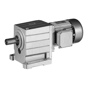
- Page 1 G... GST, GFL, GKS/GKL, GKR, GSS Operating Instructions Gearboxes / geared motors ...
- Page 2 Please read these instructions before you start working! Follow the enclosed safety instructions. 0Abb. 0Tab. 0...
-
Page 3: Table Of Contents
Breather position, oil filling screw and drain plug ....5.3.12 Gearbox with compensation container for mounting position C ..Lenze • BA 12.0023 • 9.0... - Page 4 ..........Lenze • BA 12.0023 • 9.0...
-
Page 5: About This Documentation
• The documentation must always be complete and in a perfectly readable state. Tip! Information and tools concerning the Lenze products can be found in the download area at www.lenze.com Validity This documentation applies to the gearbox types:... -
Page 6: Document History
Note ”Geared motors for deep-freeze application” inserted in ”Safety instructions” chapter Values in Tab. 3 added Values in table of chapter 8.2.6 added for GST 11/2015 TD09 Operating condition: ”Mechanical” deleted .S>, Supplement: encoder code, 22 ”Auxiliary tool” table updated Lenze • BA 12.0023 • 9.0... -
Page 7: Conventions Used
Wildcard Wildcard for options, selection data Terminology used Term Describes the following Gearboxes Gearbox of product range G Drive system Drive systems with gearboxes G and other Lenze drive components Lenze • BA 12.0023 • 9.0... -
Page 8: Notes Used
Application notes Pictograph and signal word Meaning Note! Important note to ensure trouble-free operation Tip! Useful tip for easy handling Reference to another document Lenze • BA 12.0023 • 9.0... -
Page 9: Safety Instructions
This is vital for safe and trouble-free operation and for achieving the specified product features. • Only qualified skilled personnel are permitted to work with or on Lenze drive and automation components. According to IEC 60364 or CENELEC HD 384, these are persons ... - Page 10 • check that all component parts with a loose fastening are secured or removed; • tighten all transport aids (eye bolts or support plates). Use an appropriate means of transport and lifting equipment! ( 25) Lenze • BA 12.0023 • 9.0...
- Page 11 Corrosion protection Lenze offers paints with different resistance characteristics for drive systems. Since the resistance may be reduced when the paint coat is damaged, defects in paint work (e.g.
-
Page 12: Application As Directed
– ... in aggressive environments (acid, gas, vapour, dust, oil) – ... in water – ... in radiation environments Note! Increased surface and corrosion protection can be achieved by using adapted coating systems. Lenze • BA 12.0023 • 9.0... -
Page 13: Residual Hazards
• Design with plug: – Never disconnect plug when energised! Otherwise, the plug can be destroyed. – Switch off power supply and inhibit controller prior to disconnecting the plug. Lenze • BA 12.0023 • 9.0... -
Page 14: Disposal
Safety instructions Disposal Fire protection • Fire hazard – Prevent contact with flammable substances. Disposal Sort individual parts according to their properties. Dispose of them as specified by the current national regulations. Lenze • BA 12.0023 • 9.0... -
Page 15: Product Description
Product description Identification Product description • The most important technical data is given on the nameplate. • The product catalogues contain further technical data. Identification 1-stage 2-stage 3-stage 2-stage 3-stage 3-stage 4-stage Lenze • BA 12.0023 • 9.0... -
Page 16: Product Features
Helical gearbox Shaft-mounted helical Spur gear Spur gear gearbox Spur gear Helical-bevel gearbox Spur gear Bevel gear Bevel gearbox Helical-worm gearbox Spur gear Worm • The torque reaction must be supported in a suitable manner. Lenze • BA 12.0023 • 9.0... - Page 17 Solid shaft: 3, 5, 8 (3+5) Flange: 3, 5, 8 (3+5) Terminal box, Motec, plug: 2, 3, 4, 5 Hollow shaft: 0 Without flange: 0 Without terminal box, Motec, plug: 0 Hollow shaft with shrink disc: 3, 5 Lenze • BA 12.0023 • 9.0...
-
Page 18: Nameplate
14.3 cos j 20.2 16.6 10.2 10.1 20.1 Three-phase AC motor with standard output flange 14.2 16.1 14.1 16.2 14.3 r/min 16.3 16.4 16.4 16.5 10.1 20.1 16.5 cos j 10.2 10.3 16.6 16.7 Lenze • BA 12.0023 • 9.0... - Page 19 Partial load efficiencies for 50Hz operation at a rated power of 50% and 75% CC number Department of Energy (optional) Permissible ambient temperature (e.g. Ta 40°C) Standstill current (ampere locked rotor ALR) Plug design (number of poles) Lenze • BA 12.0023 • 9.0...
- Page 20 Mounting position / position of the system blocks Rated torque/speed Rated torque Rated speed/rated frequency Operating factor (indicated when <1.0) Lubricant amount / type of lubricant Ratio Material number / serial number Bar code Order number Additional information Additional customer data Lenze • BA 12.0023 • 9.0...
-
Page 21: Gearbox Code
Foot mounting, with centering Foot mounting, without centring Without foot, with centering Without foot, without centering Without flange With flange (through holes) With flange (threaded holes) Drive size Example Motor 071N32; 080-12 Mounting flange/free drive shaft Lenze • BA 12.0023 • 9.0... -
Page 22: Encoder Code
For safety function HTL (for incremental encoders) Hiperface (for absolute value encoders) EnDat sin/cos 1 V Safety integration level (SIL) Note! If feedback systems for safety functions are used, the manufacturer’s documentation must be observed! Lenze • BA 12.0023 • 9.0... -
Page 23: Transport Weights
< 600 < 700 < 850 < 400 < 700 < 750 < 850 < 950 < 1100 < 625 Tab. 1 Transport weights in [kg]; values may differ from table value Lenze • BA 12.0023 • 9.0... -
Page 24: Technical Data
> 1000 m amsl < 4000m amsl with power reduction, see catalogue Humidity Relative humidity 85 %, without condensation Electrical The motor connection type depends on the controller Length of the motor cable inverter instructions Length of cable for speed feedback Lenze • BA 12.0023 • 9.0... -
Page 25: Mechanical Installation
Transport equipment for gearboxes As of size 05, Lenze GST, GKS and GSS gearboxes are as standard available with a transport thread for eye bolts according to DIN 580. The thread position can be seen from the below figures. - Page 26 Use additional appropriate lifting aids, if required, to achieve a direction of loading which is as vertical as possible (highest payload). Secure lifting aids against shifting! Stop! Observe load carrying capacity! Standing beneath floating loads is prohibited! Lenze • BA 12.0023 • 9.0...
-
Page 27: Storage
Install gearbox in mounting position A. – Fill gearbox up to the top vent hole / oil hole with the oil grade specified (see nameplate). Then mount the locking screw and ventilation unit (do not activate) again. Lenze • BA 12.0023 • 9.0... -
Page 28: Specification Of The Direction Of Rotation
2. Remove breathing / oil filler plug. 3. Completely drain lubricant. 4. Screw in oil drain plug. 5. Fill in amount of oil for the mounting position provided (according to nameplate). 6. Screw in breathing / oil filler plug. Lenze • BA 12.0023 • 9.0... -
Page 29: General Information About The Assembly Of Drive Systems
Condensation drain hole Note! Lenze delivers motors with condensation drain holes with sealed condensation drain holes. The holes are sealed with a plastic plug or a locking screw. This does not affect the type of protection and the motor is protected against the ingress of foreign substances during transport and operation. -
Page 30: Attachment Of Motors To Gearboxes With Bearing Housing (Input Design N)
B6 x 6 x 18 10.5 30-60 B8 x 7 x 18 30-60 Tab. 3 Attachment of motors to gearboxes with mounting flange * Use original key for the motor Key for standard hub and clamping hub Lenze • BA 12.0023 • 9.0... -
Page 31: Coupling Hubs
4. Lay spider in the coupling claw on the gearbox side. 5. Align claws of the motor-side coupling hub with its counterpart. 6. Slowly push on motor, and bolt on to the gearbox flange. Lenze • BA 12.0023 • 9.0... - Page 32 5. Lay spider in the coupling claw on the gearbox side. 6. Align claws of the motor-side coupling hub with its counterpart. 7. Slowly push on motor, and bolt on to the gearbox flange. Lenze • BA 12.0023 • 9.0...
-
Page 33: Attachment Of Gearboxes With Hollow Shafts And Keyway
Take up forces only via the hollow shaft, and not via gearbox housing. 2. Secure the gearbox axially: – The hollow shaft has snap ring grooves for axial securing. Parts used to fix the shaft are not included in the scope of supply. Lenze • BA 12.0023 • 9.0... - Page 34 With the bevel gearbox, the hollow shafts are turned free in the middle of the hollow shaft, i.e. the bore diameter is 0.1 mm higher here! A sufficient length of the machine shaft must be observed. GKR size l max. Tab. 5 Dimensions in mm Lenze • BA 12.0023 • 9.0...
-
Page 35: Mounting The Shrink Disc With A Rotating Cover
Mounting the shrink disc Depending on the design, the shrink discs may be equipped with a rotating cover (protective cap, pos. 1). Note! This cover is fitted to the shrink disc on delivery. Lenze • BA 12.0023 • 9.0... - Page 36 GT-GNG-003.iso/dms Fig. 8 Explanation: ”one after the other” Tip! Several (in general more than 5 ) passes are necessary until the full tightening torque is reached at all screws! Lenze • BA 12.0023 • 9.0...
- Page 37 8. Push protective cap (1, Fig. 7) onto the shrink disc. Tip! For finding out the cause of non-reached torques of the shrink disc connection, please go through the troubleshooting list in chapter 9. Lenze • BA 12.0023 • 9.0...
- Page 38 • the connection is spinning due to overload or a too low friction factor and fretting corrosion has occurred, • the shrink disc has been tightened too much leading to a plastic deformation of components, • the components are corroded. Lenze • BA 12.0023 • 9.0...
-
Page 39: Mounting The Fixed Cover
120°. 2. Fit seal (4) between flange and protective cap (1). 3. Fasten the protective cap (1) over the reducing bushes (3) on the flange using three cheese head screws (2). Lenze • BA 12.0023 • 9.0... -
Page 40: Gearboxes With Breathers
Stop! • Rotate gearbox to the mounting position shown on the nameplate (( 18)und ( 41). • With gearbox types GST-3, GFL-3, GSS-3 and GKS-4, the pre-stage is separately ventilated! (Exception: size 06) Lenze • BA 12.0023 • 9.0... -
Page 41: Breather Position, Oil Filling Screw And Drain Plug
Helical gearbox GST 05 ... 09-1 GT-GNG-GST-1-001_A-F.iso/dms A...F Mounting positions Oil drain plug On both sides Oil-control plug On the opposite side Pos. 1 Standard Breathing / oil filler plug Pos. 2 only GST05-1A 080C22 with: Lenze • BA 12.0023 • 9.0... - Page 42 Standard On both sides Pos. 2 only GST05-2M V 090C with: On the opposite side GST05-2M V 100C Breathing / oil filler plug GST06-2M V 112C Oil drain plug GST07-2M V 160C Oil-control plug Lenze • BA 12.0023 • 9.0...
- Page 43 Mounting positions Pos. 1 Standard On both sides Pos. 2 only GST05-3M V 090C with: On the opposite side GST05-3M V 100C Breathing / oil filler plug GST06-3M V 112C Oil drain plug Oil-control plug Lenze • BA 12.0023 • 9.0...
- Page 44 Standard Pos. 2 only On both sides GFL05-2M 090C with: On the opposite side GFL05-2M 100C Breathing / oil filler plug GFL06-2M 112C Oil drain plug GFL07-2M 160C Oil-control plug Lenze • BA 12.0023 • 9.0...
- Page 45 Mounting positions Pos. 1 Standard On both sides Pos. 2 only GFL07-3M 090C with: On the opposite side GFL07-3M 100C Breathing / oil filler plug GFL09-3M 112C Oil drain plug Oil-control plug Lenze • BA 12.0023 • 9.0...
- Page 46 Pos. 1 Standard GKS05...07 with torque plate on the foot Pos. 2 only for: GKS05-3M 090C in position 4 GKS05-3M 100C GKS06-3M 112C Ventilation / oil filler plug GKS07-3M 160C Lenze • BA 12.0023 • 9.0...
- Page 47 On the opposite side Pos. 1 Standard GKS05...07 with torque plate on the foot Pos. 2 only for: GKS07-4M 090C in position 4 GKS07-4M 100C GKS09-4M 112C Ventilation / oil filler plug Lenze • BA 12.0023 • 9.0...
- Page 48 On the opposite side Pos. 1 Standard With torque plate on the foot in position 4 Pos. 2 only for: GSS05-2M 090C GSS05-2M 100C GSS06-2M 112C Ventilation / oil filler plug GSS07-2M 160C Lenze • BA 12.0023 • 9.0...
- Page 49 Oil control plug On the opposite side Pos. 1 Standard With torque plate on the foot in position 4 Pos. 2 only for: GSS07-3M 090C GSS07-3M 100C Ventilation / oil filler plug Lenze • BA 12.0023 • 9.0...
- Page 50 Mechanical installation Mounting Breather position, oil filling screw and drain plug Bevel gearbox GKR GT-GNG-GKR-2-001_A-F.iso/dms A...F Mounting positions Breathing / oil filler plug Lenze • BA 12.0023 • 9.0...
- Page 51 Helical-bevel gearbox GKL07...09-3 GT-GNG-GKL-001.iso/dms A...F Mounting positions Breathing / oil filler plug On both sides Oil drain plug On the opposite side Oil-control plug Pos. 1 or 2 Depending on version Sealing plug without function Lenze • BA 12.0023 • 9.0...
-
Page 52: Gearbox With Compensation Container For Mounting Position C
4. Use hexagon nut (7) to bolt the breather element (6) to the cover (5). 5. Mount cover (5) and seal (8) to the housing (4). Stop! For transport the compensation reservoir must be removed and the plug must seal the gearbox (pos. 9). Lenze • BA 12.0023 • 9.0... -
Page 53: Electrical Installation
To correctly connect the motor options, e. g. brakes or feedback systems, please observe: • the notes in the corresponding terminal box • the notes in the corresponding operating instructions • the technical data on the corresponding motor nameplate. Lenze • BA 12.0023 • 9.0... -
Page 54: Commissioning And Operation
• In the event of faults: – shut down the drive, – check the troubleshooting table. If the fault cannot be remedied, please contact the Lenze customer service. Lenze • BA 12.0023 • 9.0... -
Page 55: Maintenance
Maintenance intervals Maintenance When they are delivered, Lenze gearboxes and geared motors are filled with a drive and type-specific lubricant so that they are ready for production. This initial filling corresponds to a lubricant from the column of the respective Lenze gearbox type. When the order is placed, the mounting position and the design are the decisive factors for the lubricant amount. - Page 56 Maintenance Maintenance intervals Note! If ambient temperatures are <-20°C or >+40°C, please contact Lenze! Observe increased starting torques at low temperatures! 16000 h 25000 h 1000 10000 100000 GT-GNG-002.iso/dms Fig. 13 Lubricant diagram Oil sump temperature [°C] Synthetic oil CLP HC/CLP PG ...
-
Page 57: Maintenance Operations
If the condensation drain holes are not sealed again, the IP enclosure of the motor will be reduced. For horinzontal motor shafts to IP23 and for vertical motor shafts to IP20. Fig. 14 Motor with condensation drain holes Condensation drain holes Lenze • BA 12.0023 • 9.0... -
Page 58: Lubricate Roller Bearings
Maintenance Maintenance operations Lubricate roller bearings 8.2.2 Lubricate roller bearings The roller bearings on motors and gearboxes from Lenze are filled with the greases listed below: Ambient temperature Manufacturer Type Gearbox roller bearing -30 °C ... +50 °C Fuchs Renolit H 443 GST, GFL, GKS, GKR, GKL -30 °C ... -
Page 59: Table Of Lubricants
Lenze lubricant table does not mean that Lenze is liable for these lubricants or damages resulting from incompatibilities of materials used. For Lenze drives, the lubricants listed in the lubricant table on the following page are permitted. Special lubricants must be used, for instance for longtime storage or special operating conditions. - Page 60 CLP HC VG 320 Carter SH 320 CLP HC VG 460 Cassida Fluid GL 460 CLP PG VG 220 Cassida Fluid GL 220 CLP HC VG 46 Cassida HF 46 Lenze • BA 12.0023 • 9.0...
-
Page 61: Replacing The Lubricant
4. Reinsert drain plug (if necessary, replace seal). 5. Fill in lubricant through filler hole (quantities see nameplate). 6. Screw in breathing / oil filler plug. 7. Dispose of waste oil according to the applicable regulations. Lenze • BA 12.0023 • 9.0... -
Page 62: Lubricant Quantity
Maintenance Maintenance operations Lubricant quantity 8.2.5 Lubricant quantity Stop! At drive speeds below 200 rpm the amount of lubricant may need to be increased. Consultation with Lenze is required. Lenze • BA 12.0023 • 9.0... - Page 63 GFL14 M≥132 M≥132 M≥132 A≥112 A≥112 A≥112 N≥1G N≥1G N≥1G W≥1G W≥1G Tab. 9 Amount of lubricant in litres Drive 90...132 Motor size A, M, N, W Drive-end version 1A ...2K Drive size Lenze • BA 12.0023 • 9.0...
- Page 64 M≥132 M≥132 M≥132 A≥112 A≥112 A≥112 N≥1G N≥1G N≥1G W≥1G W≥1G W≥1G Tab. 10 Amount of lubricant in litres Drive 90...132 Motor size A, M, N, W Drive-end version 1A ...2K Drive size Lenze • BA 12.0023 • 9.0...
- Page 65 N≥1G N≥1G N≥1G N≥1G W≥1G W≥1G W≥1G W≥1G W≥1G GST11 10.5 GST14 Tab. 11 Amount of lubricant in litres Drive 90...132 Motor size A, M, N, W Drive-end version 1A ...2K Drive size Lenze • BA 12.0023 • 9.0...
- Page 66 GKS04 GKS05 GKS06 GKS07 GKS09 GKS11 11.5 GKS14 Helical-worm gearbox GSS -2; -3 GSS04 GSS05 GSS06 GSS07 Helical-bevel gearbox GKL GKL07 GKL09 10.4 Tab. 12 Amount of lubricant in litres Drive Lenze • BA 12.0023 • 9.0...
- Page 67 0.7 / 0.8 * GKR05 1.5 / 1.6 * GKR06 3.0 / 3.2 * Mounting position GKR03 0.35 0.35 0.35 GKR04 GKR05 GKR06 Tab. 13 Amount of lubricant in litres with version VK at the output end Lenze • BA 12.0023 • 9.0...
-
Page 68: Lubricant Amounts For Combinable Mounting Positions
A E F 0.35 0.45 0.45 0.70 0.60 0.95 Shaft-mounted helical gearbox GFL04 ... 05-2; V Types V R; V Mounting position GFL04 GFL05 A B E Type V A B E 0.35 Lenze • BA 12.0023 • 9.0... -
Page 69: Repair
Mounting position GKR03 GKR04 GKR05 B C D E 0.35 Type V 0.35 B D E 0.35 Repair • We recommend having all repairs carried out by the Lenze customer service. Lenze • BA 12.0023 • 9.0... -
Page 70: Spare Parts List For Geared Motors
Maintenance Spare parts list for geared motors Lenze • BA 12.0023 • 9.0... -
Page 71: Spare Parts List For Gearboxes And Gearboxes With Variable Speed Drives
Maintenance Spare parts list for gearboxes and gearboxes with variable speed drives Lenze • BA 12.0023 • 9.0... -
Page 72: Order Form
Pre-stage 19BA Shrink disc cover Intermediate cover 20BA Hollow shaft cover Motor 21BA Seal 22BA Seal Fan cover 23BA Seal Spring-applied brake 24BA Seal 10BA Blower 25BA Planetary variable speed drive 11BA Mounting flange Lenze • BA 12.0023 • 9.0... -
Page 73: Troubleshooting And Fault Elimination
If any malfunctions should occur during operation of the drive system, please check the possible causes using the following table. If the fault cannot be eliminated by one of the listed measures, please contact the Lenze Service. Fault Possible cause... - Page 74 Notes Lenze • BA 12.0023 • 9.0...
- Page 75 Notes Lenze • BA 12.0023 • 9.0...
- Page 76 © 11/2015 | BA 12.0023 | .S>, | 9.0 | TD09 Lenze Drives GmbH Postfach 10 13 52, 31763 Hameln Breslauer Straße 3, 32699 Extertal GERMANY HR Lemgo B 6478 +49 5154 82-0 +49 5154 82-2800 ...
Need help?
Do you have a question about the GKS Series and is the answer not in the manual?
Questions and answers