Lenze g500-H Mounting And Switch-On Instructions
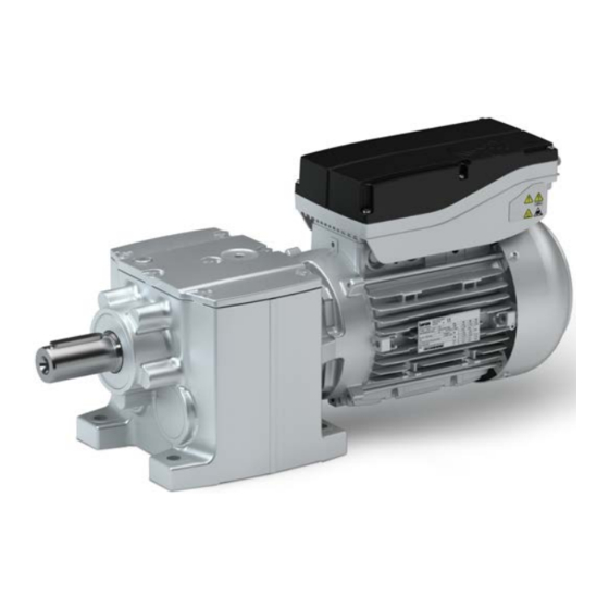
Mains-operated geared motors
Hide thumbs
Also See for g500-H:
- Manual (168 pages) ,
- Project planning (104 pages) ,
- Mounting instructions (4 pages)

Subscribe to Our Youtube Channel
Related Manuals for Lenze g500-H


Summary of Contents for Lenze g500-H
- Page 1 Mounting and switch-on instructions EN Mains-operated geared motors g500-H helical geared motor / Smart Motor m300-E...
-
Page 3: Table Of Contents
Contents Contents About this document Document description Further documents Notations and conventions Safety instructions Basic safety instructions Application as directed Residual hazards Product information Identification of the products Nameplates Product codes Equipment Transport Storage Mechanical installation Important notes Preparation Installation Mounting positions Ventilation Dimensions... - Page 4 Contents Technical data Standards and operating conditions Conformity and approvals Protection of persons and device protection EMC data Environmental conditions Electrical supply conditions Motor data Rated data Ecodesign Directive Environmental notes and recycling...
-
Page 5: About This Document
The documentation must always be complete and in a perfectly readable state. • Further documents Information and tools with regard to the Lenze products can be found on the Internet: www.Lenze.com à Downloads... -
Page 6: Notations And Conventions
About this document Notations and conventions Notations and conventions Conventions are used in this document to distinguish between different types of information. Numeric notation Decimal separator Point Generally shown as a decimal point. Example: 1 234.56 Warnings UL Warnings Are used in English and French. UR warnings Text Engineering Tools... -
Page 7: Safety Instructions
Safety instructions Basic safety instructions Safety instructions Basic safety instructions Disregarding the following basic safety instructions and safety information may lead to severe personal injury and damage to property! Only use the product as directed. • Never commission the product in the event of visible damage. •... -
Page 8: Residual Hazards
Safety instructions Residual hazards Residual hazards Even if notes given are taken into consideration and protective measures are implemented, the occurrence of residual risks cannot be fully prevented. The user must take the residual hazards mentioned into consideration in the risk assessment for his/her machine/system. - Page 9 Safety instructions Residual hazards Gearbox protection Excessive vibration accelerations and resonances will damage the gearbox. • Do not operate the gearbox at vibration accelerations > 2 g (20 m/s ) of the machine. Do not operate the gearbox in the resonance range of the machine. Excessive torques will damage the gearboxes.
-
Page 10: Product Information
Product information Identification of the products Nameplates Product information Identification of the products Nameplates The nameplate is attached to the motor. 16.1 16.2 16.4 16.5 r/min 16.3 14.1 cos j 16.6 14.2 16.10 10.3 10.2 20.1 Position Contents Position Contents Manufacturer / production location Rated data for various frequencies Type of motor / standard... -
Page 11: Product Codes
Product information Identification of the products Product codes Product codes Gearbox product code Example Product type Gearboxes Product family Generation Gearbox type Helical gearbox Output torque 45 Nm 100 Nm 140 Nm 210 Nm 320 Nm 450 Nm 600 Nm 850 Nm 1500 Nm 3000 Nm... - Page 12 Product information Identification of the products Product codes Motor product code Example Meaning Variant Product code Product family Motor Product type Smart Motor Cooling Integral fan Internal key Built-on accessories Without built-on accessories Brake Size Overall length Number of pole pairs 4-pole motors Design types Internal key...
-
Page 13: Equipment
Product information Equipment Equipment The following figure provides an overview of the elements and connections on the product. Their position, size and appearance may vary. Ventilation (depending on the mounting position) Oil filler plug (depending on the mounting position) Remove oil control plug (depending on the mounting position) Output flange Output shaft... -
Page 14: Transport
Transport Transport Ensure appropriate handling. • Make sure that all component parts are securely mounted. Secure or remove loose • component parts. Only use safely fixed transport aids (e.g., eye bolts or support plates). • Do not damage any components during transport. •... - Page 15 Transport Position of the eye bolt G50AH045 ... G50BH114 G50BH121 ... G50BH230 Thread Load carrying 1200 1800 capacity...
-
Page 16: Storage
Storage Storage Storage up to one year: Observe the climatic conditions according to the technical data • 4Environmental conditions ^ 56 Store in a dry, low-vibration environment (V < 0.2 mm/s) without aggressive atmosphere • in the interior Protect from dust, shocks and sunlight •... -
Page 17: Mechanical Installation
Ambient media − especially chemically aggressive ones − may damage shaft sealing rings, • lacquers and plastics. Lenze offers special surface and corrosion protection in this case. • Only install the gearbox in the mounting position shown. •... -
Page 18: Installation
Mechanical installation Installation Mounting positions Installation The mounting surfaces must be plane, torsionally rigid and free from vibrations. • The mounting areas must be suited to absorb the forces and torques generated during • operation. Ensure an unhindered ventilation. • For versions with a fan, keep a minimum distance of 10 % from the outside diameter of the •... -
Page 19: Ventilation
Mechanical installation Installation Ventilation Ventilation No ventilation is required for the gearboxes G50AH045 …BH121. The gearbox G50BH121 can optionally be fitted with ventilation units. From G50BH132onwards, the gearboxes are supplied with ventilation units as standard. Gearboxes that are delivered with a ventilation unit are provided with a label. Remove the transport locking device on the vent valve before initial commissioning. - Page 20 Mechanical installation Installation Ventilation Mounting position M4 (C) Mounting position M5 (F) Mounting position M6 (E) Filling and ventilation Control ① ② Drain G50BH121 ① G50BH132 ② G50BH145...
- Page 21 Mechanical installation Installation Ventilation G50BH160 ... BH230 Mounting position M1 (A) Mounting position M2 (D) Mounting position M3 (B) Filling and ventilation Check Drain...
- Page 22 Mechanical installation Installation Ventilation Mounting position M4 (C) Mounting position M5 (F) Mounting position M6 (E) Filling and ventilation Control Drain Gearbox with oil compensation reservoir for mounting position M4 (C) In order to guarantee a reliable lubrication of the toothed parts in mounting position M4 (C) (motor is on the gearbox vertical from the top), a high filling level is required in the gearbox.
-
Page 23: Dimensions
Mechanical installation Dimensions Dimensions Dimensions are contained in the configuration document. Mounting Transmission elements Fit or remove transmission elements only using suitable equipment. • For fitting the transmission elements use the center hole in the shaft. • Avoid impacts and shocks. •... -
Page 24: Electrical Installation
Electrical installation Important notes Electrical installation Important notes DANGER! Risk of injury and risk of burns from dangerous voltage Power terminals may also carry voltage in the switched-off state or when the motor is stopped and may cause life-threatening cardiac arrhythmia and serious burns. ▶... -
Page 25: Mains Connection
Electrical installation Mains connection Connection according to EN Mains connection Connection according to EN The following data is valid for a three-phase mains connection with 400 V. Mains connection with QUICKON connector Motor MSEMA☐☐063-42 MSEMA☐☐080-32 Connection Laying system Connection type QUICKON connector Cable type Flexible... - Page 26 Electrical installation Mains connection Connection according to EN Single drive connection according to EN IEC 60204‑1 3/N/PE AC 400/480 V SELV/PELV F1 … F3 F1 … F3 DC 24 V (+19.2 … +28.8 V) max. 50 mA n. c. L2 L3 Rb1 Rb2 L2 L3 Rb1 Rb2...
- Page 27 Electrical installation Mains connection Connection according to EN Group drive connection according to EN IEC 60204‑1 F1 … F3 PE L1 L2 L3 PE L1 L2 L3 PE L1 L2 L3 PE L1 L2 L3 PE L1 L2 L3 Max. total rated mains currents at 40 °C for different cable cross-sections Cable installation in accordance EN IEC 60204‑1...
-
Page 28: Connection According To Culus
Electrical installation Mains connection Connection according to cULus Connection according to cULus The following data is valid for a three-phase mains connection with 480 V. Mains connection with QUICKON connector Motor MSEMA☐☐063-42 MSEMA☐☐080-32 Connection Connection type QUICKON connector Cable cross-section Typ. - Page 29 Electrical installation Mains connection Connection according to cULus WARNING! ▶ UL marking ▶ Use 75 °C copper wire only, except for control circuits. ▶ Maximum conductor size is AWG14. ▶ Cord connected drives are for use only in NFPA 79 applications. ▶...
- Page 30 Electrical installation Mains connection Connection according to cULus Fuse data (F1 ... F3) Motor MSEMA☐☐063-42 MSEMA☐☐080-32 Cable installation in accordance NFPA 70, NFPA 79 with Fuse Standard UL 248 Typ. Rated current Max. rated current Semiconductor fuse Standard UL 248 Typ.
- Page 31 Electrical installation Mains connection Connection according to cULus Max. total rated mains currents at 40 °C for different cable cross-sections Cable installation in accordance NFPA 70, NFPA 79 with Main cable Cable cross-section Stub Cable cross-section Fuse Typ. Rated current Max.
-
Page 32: Motor Connection
Electrical installation Motor connection Connection via terminal box Motor connection To connect the motor correctly, you must follow: The notes in the terminal box of the motor. • The notes in the configuration document of the motor. • The technical data on the motor nameplate. •... -
Page 33: Connection Via M12 Connector
Electrical installation Motor connection Connection via M12 connector Connection via M12 connector NOTICE In the "DI/DO-GND bridged" version, the masses of the control terminal X1 and X2 (GND-I and GND-O) are connected to each other. If only one speed is used, the connection to X2 is sufficient. -
Page 34: Commissioning
Commissioning Commissioning You have two options to adapt the Lenze Smart Motor to the applications: Preconditions NFC-capable smartphone or tablet • Android version from V3.0 • Lenze app "Lenze Smart Motor" Download from www.Lenze.com or from the Google store • Deenergize motor •... - Page 35 STOP: 0 rpm Output speed 2 [500/i ... 2600/i] rpm CW rotation: > 0 rpm Output speed 3 Lenze Smart Motor with gearbox: The ratio i is Output speed 4 taken into account when calculating the output Output speed 5 speed.
- Page 36 Commissioning Device data Parameter Value Comment Designation Delivery Setting range Material number depending on the order [number] Drive identification Device types [Text] Firmware version [Text] Hardware Version [Text] Motor [Text] Gearboxes [Text] Ratio [number] Brake [Text] Serial number [Text] Activating speeds Output speed Activate output speed Parameter...
-
Page 37: Before Initial Switch-On
Commissioning Before initial switch-on Advanced settings Parameter Value Comment Name Delivery Setting range boost 0.0 % [0.0 ... 100.0] % Effective only if Energy saving function = On: • Boost of the motor voltage in the range of low speeds. •... -
Page 38: Functional Test
Commissioning Functional test Functional test After commissioning, check all individual functions of the drive: Rotating direction in decoupled state • Torque behavior and current consumption • Brake function • During operation, carry out inspections on a regular basis. Pay special attention to: Unusual noises •... -
Page 39: Maintenance
Maintenance Maintenance WARNING! Risk of injury due to non-compliance with the following safety measures Disregarding the following safety measures may lead to severe personal injury and damage to property. ▶ Only work on the drive system when it is de-energised. ▶... -
Page 40: Maintenance Intervals
Maintenance Maintenance intervals Maintenance intervals Geared motor/gearbox Time interval Measures Description of the operations After assembly and after 3 hours , check fastening. Check all fixing screws on the gearbox (foot, flange and shrink disc fixing ...) for tightness. On the first day, then every General check Pay attention to unusual operating noises, vibrations and impermissibly high month... - Page 41 Maintenance Maintenance intervals Determine change intervals for lubricants 1. Measure the lubricant temperature at the drain plug 2. Add 10 C 3. Determined the change interval from the diagram Position Of the drain plug 4Ventilation ^ 19 1000 50000 10000 Oil sump temperature [°C] Synthetic oil: CLP HC/CLP PG Change interval in operating hours [h]...
-
Page 42: Maintenance Work
Maintenance Maintenance work Maintenance work Check the oil level NOTICE ▶ Check the oil level in cold condition! Check the oil level by means of the displayed dipsticks. Depending on the gearbox type and the mounting position (M1 ... M6), make these according to the following templates. The gearbox type and mounting position are indicated on the nameplate. - Page 43 Maintenance Maintenance work Gearbox G50BH121 ... H145 Template: Dipsticks for G50BH121...
- Page 44 Maintenance Maintenance work Template: Dipsticks for G50BH132...
- Page 45 Maintenance Maintenance work Template: Dipsticks for G50BH145 How to check the lubricant level: 1. Remove the control screw at the marked position.4Ventilation ^ 19 2. Insert the dipstick through the threaded hole. Observe the position of the dipstick in the template! 3.
- Page 46 Maintenance Maintenance work Gearbox G50BH160 ... G50BH314 How to check the lubricant level: 1. Remove the control screw at the marked position.4Ventilation ^ 19 2. Insert auxiliary tool through the threaded hole. 3. Carefully pull out the auxiliary tool and determine the lubricant level. The lubricant level may be between the threaded hole and dimension "x".
- Page 47 Maintenance Maintenance work Change lubricant NOTICE Change from standard lubricant CLP or CLP HC to food grade lubricant CLP ... USDA H1. The drain holes do not always allow complete draining of the gearbox. A residual amount of the lubricant may remain in the gearbox. ▶...
- Page 48 Maintenance Maintenance work Maintenance work at the spring-applied brake NOTICE ▶ Brakes with defective armature plates, springs or flanges must be completely replaced. ▶ Before carrying out maintenance work, identify the brake and motor protection type from the nameplate. 4Nameplates ^ 10 Before working on the brake, remove the integral fan cover or blower cover on the motor.
- Page 49 Maintenance Maintenance work Stator Sleeve bolt with hexagon Armature plate Air gap Cylinder screw How to check the air gap: 1. Do not energize the brake. 2. Measure the air gap s between stator (1) and armature plate (2) in the vicinity of the cylinder screws (3) using a surface feeler gauge.
-
Page 50: Repair
First check the possible causes of malfunction according to the 4Diagnostics and fault • elimination ^ 51 If the fault cannot be remedied using one of the measures listed, please contact the Lenze • service department. The contact data can be found on the rear of this documentation. -
Page 51: Diagnostics And Fault Elimination
The fault is entered in the history buffer. • Lenze Smart Motor without brake: The motor is switched off and coasts down. • Lenze Smart motor with brake: The motor is switched off; the brake is applied. Warning The fault is entered in the history buffer. -
Page 52: Malfunctions
2. Connect and disconnect mains. 3. Rewrite parameter set. RFID data version invalid (PS04) Incompatible software version Update Lenze App or EASY Starter. Missing mains phase (SU02) A mains phase of a three-phase supply • Check mains connection. has failed. Reliable detection from an •... - Page 53 Reduce load Check assignment drive - machine Motor runs, gearbox does not Coupling components are missing or defective Check mounting Gearbox is defective Inform Lenze Service Clutch disengaged Engage the clutch Unusual running noises Overload Reduce load Check assignment drive - machine...
-
Page 54: Technical Data
The Electrical Equipment (Safety) Regulations 2016 S.I. 2021/745 The Ecodesign for Energy-Related Products and Energy Information Regulations 2021 Approvals GB Standard 12350-2009 For USA and Canada (requirements of the CSA 22.2 No.14) Industrial Control Equipment, Lenze File cULus UL 61800-5-1 No. E132659... -
Page 55: Protection Of Persons And Device Protection
Technical data Standards and operating conditions Protection of persons and device protection Protection of persons and device protection Protection class EN IEC 60529,EN IEC Information applies to the mounted and ready- IP55 60034-5 for-use state Type 12 NEMA NEMA 250 Type 4 indoor only Depending on the configuration Insulation resistance... -
Page 56: Environmental Conditions
Technical data Standards and operating conditions Environmental conditions Environmental conditions Climate 1K3 (-30 ... +60°C) <3 months Storage EN 60721-3-1:1997 1K3 (-30 ... +40 °C) >3 months Transport EN 60721-3-2:1997 2K3 (-30 ...+70 °C) EN 60721-3-3:1995 + Operation 3K3 (-30 ...+40 °C) Operation A2:1997 Site altitude... -
Page 57: Motor Data
η Efficiency at 75 % rated load η Efficiency at 50 % rated load Efficiency level Manufacturer's name Lenze SE · Hans-Lenze-Str. 1 · 31855 Aerzen · GERMANY Commercial register number Hannover HRB 204803 Model identifier of the MSEMA□□063-42 MSEMA□□080-32... -
Page 58: Environmental Notes And Recycling
Lenze products and their packaging: Lenze products are partly subject to the EU Directive on the restriction of certain hazardous substances in electrical and electronic equipment 2011/65/EU: RoHS Directive [UKCA: S.I. 2012/3032 - The Restriction of the Use of Certain Hazardous Substances in Electrical and Electronic Equipment Regulations 2012]. - Page 60 Lenze SE Postfach 101352 · 31763 Hameln Hans-Lenze-Straße 1 · 31855 Aerzen GERMANY Hannover HRB 204803 Phone +49 5154 82-0 Fax +49 5154 82-2800 sales.de@lenze.com www.Lenze.com © 11/2021 · 1.0 · www.Lenze.com...
Need help?
Do you have a question about the g500-H and is the answer not in the manual?
Questions and answers