Table of Contents
Advertisement
Quick Links
Advertisement
Table of Contents

Related Manuals for Baader Planetarium SteelDrive II


Summary of Contents for Baader Planetarium SteelDrive II
- Page 1 SteelDrive II Focuser Technical documentation 20th December 2019 v1.100...
-
Page 2: Table Of Contents
Contents 1 Functional Overview 1.1 High precision focusing of heavy loads ......1.2 Contactless Homing Sensor . - Page 3 3.3.5 USE ENDSTOP ........3.3.6 ZEROING .
-
Page 4: Functional Overview
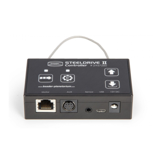
SteelDrive. Standalone Temperature Compensation SteelDrive II provides two sockets for the attachment of digital temperature sensors (one sensor is included, sockets on motor unit and controller unit). It is possible to used multiple (up to 8, use 3-pin audio Y-adapter) sensors in parrallel at one sensor socket, their temperature will be averaged (This enables the measurement the temperature eg. -
Page 5: 1A Pwm Power Output
Customizable The SteelDrive II enables power users to customize a lot of settings from temperature compensation, PID control to the adjustment of stepper motor settings. Users with multiple telescopes can use multiple motor units with only one controller one at a time. The setting for the different telescopes... -
Page 6: Standalone Handheld Usage
Chapter 2 Standalone handheld usage The SteelDrive focuser may be used standalone (without connection ot another PC). The functions available in standalone mode are: Continuous focuser movement. Focuser jogging movement. Single step movement. Homing/Zeroing Save outer limit. Save focus position. Goto saved focuser position. -
Page 7: Modes Of Operations
Figure 2.1: SteelDrive keypad Modes of operations The available keypad functions are structured in five modes of operation: NORMAL mode Continuous focuser movement Goto saved position JOG mode Focuser jogging SINGLE STEP mode Single step movement SET mode Zeroing Save limit Save position OVERRIDE LIMITS mode Continuous focuser movement ignoring the limits... -
Page 8: Usage
5. OVERRIDE LIMITS mode: When the SET button is held 3s in SET mode, the override limits mode is activated (LED2 blinking fast). The saved maximum travel limit and the homing sensor are NORMAL mode) Usage 2.3.1 Setup Assume the motor unit was mounted to the SteelTrack Diamond focuser and connected to the SteelDrive controller. - Page 9 STEP mode (LED1 and LED2 are lit). Press OUT in order to move the focuser one step (approx. 0.027 mm) outwards (with the Baader Planetarium Diamond SteelTrack, the gear-ratio of other focuser may be different). Press IN to move the focuser approx. 2.275 m inwards.
-
Page 10: Override Limits
2.3.6 Override limits In order to override a set limit, enter the NO LIMITS mode, by pressing SET once (entering the SET mode, LED2 is lit) and then holding SET button again for 3s. When LED2 is blinking fast, the set limits are ignored while moving with . -
Page 11: Button Function Overview
Button function overview NORMAL mode SET mode JOG mode SINGLE STEP mode Move out Save outer limit (hold 3s) Jog out Single step out Move in Zeroing (hold 3s) Jog in Single step in Enter JOG mode Save position (hold 3s) leave JOG mode Enter NORMAL mode Enter SET mode /... -
Page 12: Communication Protocol
Chapter 3 Communication Protocol Virtual COM-Port Configuration Parameter Value baudrate 19200 bytesize 8 bit parity bit none stop bit timeout 0.1s conoff false rtscts false dsrdtr false Always append CR+LF. Settings for the RS232 terminal programm Termite 3.1.1 Communication protocol All characters send to the device will be echoed. -
Page 13: General Commands
General commands Set variables are persitent after reboot. Often saved variables (like absolute position) are stored in circular EEPROM buffers and only changed bits are updated in order to reduce the buffer wear. 3.2.1 Unknown commands Unknown/invalid commands are responded with: $BS ERROR: Unknown command!\r\n 3.2.2 SET commands... -
Page 14: Reboot
3.2.6 REBOOT Reboot the device. Example Command: $BS REBOOT\r\n Answer: $BS Hello World!\r\n 3.2.7 RESET Reset the device to factory defaults (except serial number) and reboot. Example Command: $BS RESET\r\n Example answer: $BS OK\r\n $BS DEBUG:FACTORY RESET...\r\n $BS DEBUG: LOADING DEFAULTS...\r\n $BS Hello World!\r\n 3.2.8 NAME... - Page 15 Example answer: $BS OK\r\n GET BKLGT Get the BKLGT digital potentiometer whiper setting, controlling the keypad illumination backlight LED brightness as well as the keypad status LED brightness. Example command: $BS GET BKLGT\r\n Example answer: $BS STATUS BKLGT:100\r\n...
-
Page 16: Focuser Related Commands
Focuser related commands 3.3.1 INFO Get information about current device state: NAME,POSITION,STATE,LIMITl Useful for polling the current device state. (key-value delimiter = ’:’, item delimiter = ’;’) STATE may be GOING UP, GOING DOWN, STOPPED, ZEROED. Zeroed means that no movement has been made after that last zeroing. -
Page 17: Zeroing
Example command: $BS SET USE_ENDSTOP:1\r\n Example Answer: $BS OK\r\n GET USE ENDSTOP Get the USE ENDSTOP setting (int 0,1). Example Command: $BS GET USE_ENDSTOP\r\n Example Answer: $BS STATUS USE_ENDSTOP:0\r\n 3.3.6 ZEROING If USE ENDSTOP is enabled, the focuser will move DOWN until the homing-sensor is activated (actually it will move downwards 32767 steps (INT16 MIN), in order to prevent the focuser from moving forever in case the sensor is defective). -
Page 18: Limit
3.3.8 LIMIT LIMIT is the maximum absolute position the focuser will travel to (in outwards direction). SET LIMIT Set the upper limit for the focuser travel range (int32). Example command: $BS SET LIMIT:10000\r\n Example Answer: $BS OK\r\n GET LIMIT Get the upper limit (int32). Example command: $BS GET LIMIT\r\n Example answer:... -
Page 19: Singlesteps
$BS GET JOGSTEPS\r\n Example answer: $BS STATUS JOGSTEPS:25\r\n SET JOGSTEPS Set the number of steps for the jogging movement. [uint32] Example command: $BS SET JOGSTEPS:50\r\n Example answer: $BS OK\r\n 3.3.11 SINGLESTEPS The SINGLESTEPS variable may be used to define another JOGGING interval instead of the default 1 step setting. -
Page 20: Current Hold
GET CURRENT MOVE Get the digital potentiometer whiper setting, controlling the stepper driver current. (uint8 [0-127]) Example command: $BS GET CURRENT_MOVE\r\n Example answer: $BS STATUS CURRENT_MOVE:35\r\n 3.3.13 CURRENT HOLD The motor current while in holding position (not moving). The CURRENT HOLD value is the digital potentiometer whiper setting controlling the reference voltage, which is inversly proportional to the stepper driver current in STOPPED state. -
Page 21: Get Movements
GET MOVEMENTS The controller saves the movements in a rolling circular buffer with size 5. Format: NB,TIME,DELTA,START,STOP,TEMP0,TEMP1,TEMP AVG,SOURCE;... NB: Sequential numbering of movement sinca last reboot. TIMESTAMP: Time [ms] since last movement. DELTA: Number of steps moved. START: Absolute position at the start of the movement in steps. STOP: Absolute position at the end of the movement in steps. -
Page 22: Temperature Compensation Related Commands
Temperature compensation related commands The build in temperature compensation is controlled with three variables. Once the temperature com- pensation is started, the temperature is saved and continuously compared to the current temperature. If the difference ∆ exceeds the set variable TCOMP DELTA and the time since the last compensa- tion movement exceeds TCOMP PERIOD, the focuser will move ∆... -
Page 23: Tcomp Delta
SET TCOMP PERIOD Set the temperature compensation period (uint32 t) [ $BS SET TCOMP_PERIOD:10000\r\n Example answer: $BS OK\r\n 3.5.4 TCOMP DELTA must be exceeded for the temperature compensation movement to be triggered. GET TCOMP DELTA Get the temperature compensation ∆ threshold [ $BS GET TCOMP_FACTOR\r\n Example answer:... - Page 24 GET TCOMP SENSOR Get the Sensor used for the temperature compensation. $BS GET TCOMP_SENSOR\r\n Example answer: $BS STATUS TCOMP_SENSOR:0\r\n SET TCOMP SENSOR Set the Sensor used for the temperature compensation. $BS SET TCOMP_SENSOR:2\r\n Example answer: $BS OK\r\n...
-
Page 25: Temperature Pwm And Pid Control Related Commands
Temperature PWM and PID Control related commands The 12V/1A PWM output may be used for dew-heaters and in conjunction with one or more tem- perature sensors, for the precise PID temperature control of instruments. 3.6.1 TEMPX Temperature of sensor nb. X. GET TEMP0 Get the current temperature from the temperatur sensor plugged into the stepper motor unit (float). -
Page 26: Pid Ctrl
SET TEMP1 OFS Set the temperature offset for the temperature sensor. (float, decimal point MUST be given!) $BS SET TEMP1_OFS:1.00\r\n Example answer: $BS OK\r\n 3.6.3 PID CTRL Enables or disables the PID control. If PID control is enabled and the PWM variable is overwritten, PID CTRL is automatically disabled. -
Page 27: Pwm
GET PID SENSOR Get the current sensor used for the PID temperature control. [0 = motor ,1 = controller ,2 = average] $BS GET PID_SENSOR\r\n Example answer: $BS STATUS PID_SENSOR:0\r\n SET PID SENSOR Set the current sensor used for the PID temperature control. [0 = motor, 1 = controller, 2 = average] $BS SET PID_SENSOR:2\r\n Example answer: $BS OK\r\n... -
Page 28: Pid Dew Ofs
3.6.8 PID DEW OFS In PID DEW OFS [ ] a constant offset for the dew heater PID control can be defined. When AUTO DEW is enabled, the PID controller will adjust the PID TARGET to the temperature mea- sured by PID SENSOR + PID DEW OFS. That means, the dew heater will be kept at a constant offset with respect to the ambient temperature. -
Page 29: Firmware Update
Chapter 4 Firmware Update The windows programm BP Steeldrive II FirmwareUpdateTool.exe is provided for updating the firmware of the SteelDriveII controller unit. Connect the SDII controller unit to the computer via the provided USB cable. Execute BP Steeldrive II FirmwareUpdateTool.exe The correct COM-Port should already be selected. -
Page 30: Pinout
Chapter 5 PinOut Motor RJ45 connection pinout The stepper motor unit is connected to the controller unit via a CAT7 LAN cable. This enables the user to easily adapt the cable length to their needs without the need of any special proprietary cable. NEVER connect either the stepper motor unit or the controller unit to a LAN network via the RJ45 port. -
Page 31: Mini Din8 Pinout
Mini DIN8 pinout The Mini-DIN 8 connector of the controller unit provides a 12V/1A PWM power output for dew heaters (Cnich RCA adapter cable ), temperature control of other instruments etc. It also provides connection with other microprocessors via SPI. Figure 5.2: Mini-DIN 8 pinout (female side) 3.5mm jack pinout The 3.5mm (audio) jacks on both, the motor and the controller unit are used for the attachment of... -
Page 32: Crc8 Checksum Calculation
CRC8 checksum calculation The Dallas/Maxim CRC8 checksum calculation algorithm is used. / ** CRC lookup table * / const uint8_t crc_array[256] = { 0x00, 0x5e, 0xbc, 0xe2, 0x61, 0x3f, 0xdd, 0x83, 0xc2, 0x9c, 0x7e, 0x20, 0xa3, 0xfd, 0x1f, 0x41, 0x9d, 0xc3, 0x21, 0x7f, 0xfc, 0xa2, 0x40, 0x1e, 0x5f, 0x01, 0xe3, 0xbd, 0x3e, 0x60, 0x82, 0xdc, 0x23, 0x7d, 0x9f, 0xc1, 0x42, 0x1c, 0xfe, 0xa0, 0xe1, 0xbf, 0x5d, 0x03, 0x80, 0xde, 0x3c, 0x62,...
Need help?
Do you have a question about the SteelDrive II and is the answer not in the manual?
Questions and answers