Table of Contents
Advertisement
Quick Links
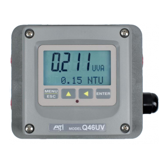
UV-254/Turbidity Monitor
Home Office
Analytical Technology, Inc.
6 Iron Bridge Drive
Collegeville, PA 19426
Phone: 800-959-0299
610-917-0991
Fax:
610-917-0992
Email: sales@analyticaltechnology.com
O & M Manual
Model Q46UV
European Office
ATI (UK) Limited
Unit 1 & 2 Gatehead Business Park
Delph New Road, Delph
Saddleworth OL3 5DE
Phone: +44 (0)1457-873-318
Fax:
+ 44 (0)1457-874-468
Email: sales@atiuk.com
Advertisement
Table of Contents

Related Manuals for ATI Technologies Q46UV


Summary of Contents for ATI Technologies Q46UV
- Page 1 O & M Manual Model Q46UV UV-254/Turbidity Monitor Home Office European Office Analytical Technology, Inc. ATI (UK) Limited 6 Iron Bridge Drive Unit 1 & 2 Gatehead Business Park Collegeville, PA 19426 Delph New Road, Delph Phone: 800-959-0299 Saddleworth OL3 5DE...
-
Page 2: Table Of Contents
Standard System ......... 4 6.11 Cal UVA Zero ......... 40 Features ..........5 6.12 Cal UVA Span ........41 Q46UV System Specifications ..... 6 6.13 Cal Turbidity Zero ......42 Q46UV Performance Specifications ..7 6.14 Cal Turbidity Span ......42 Temperature Calibration .... - Page 3 Table of Figures 1 – Q46 E ................... 8 IGURE NCLOSURE IMENSIONS 2 - W .................. 9 IGURE ALL OR IPE MOUNT BRACKET 3 - W ..................10 IGURE OUNTING IAGRAM 4 - P ..................10 IGURE OUNTING IAGRAM 5 - P ....................11 IGURE ANEL...
-
Page 4: Part 1 - Introduction
Q46UV Monitors are available in two electronic versions, an AC powered monitor with integral alarm relays and dual 4-20 mA output capability, and a 12-24 VDC unit with dual output and relays. -
Page 5: Features
Q46UV UV254/Turbidity Monitor Part 1 - Introduction Features Standard Q46 electronic transmitters are designed to be a fully isolated instruments for operation from either 90-260 VAC or 12-24 VDC power supplies. Two 4-20 mA analog outputs are standard, and a third analog output is available as an option. -
Page 6: Q46Uv System Specifications
Q46UV UV254/Turbidity Monitor Part 1 - Introduction Q46UV System Specifications Displayed Parameters UVA, 0-1.300 ABS, or UVT, 0-100% T Turbidity, 0.2-1000 NTU Sensor temperature, -10.0 to 50.0°C (23 to 122ºF) Loop current, 4.00 to 20.00 mA Sensor slope/offset Model number and software version... -
Page 7: Q46Uv Performance Specifications
Q46UV UV254/Turbidity Monitor Part 1 - Introduction Ambient Humidity 0 to 95%, indoor/outdoor use, non-condensing to rated ambient temperature range Altitude Up to 2000 m (6562 ft) Electrical Certification Ordinary Location, cCSAus (Certified to both CSA and UL standards), pollution degree 2, installation category 2... -
Page 8: Part 2 - Analyzer Mounting
Part 2 – Analyzer Mounting General All Q46 Series instruments offer maximum mounting flexibility. A bracket is included with each unit that allows mounting to walls or pipes. Choose a location that is readily accessible for calibrations and keep in mind that it will be necessary to use solutions during the calibration process. -
Page 9: Wall Or Pipe Mount
Part 2 – Analyzer Mounting Q46UV UV254/Turbidity Monitor Wall or Pipe Mount A PVC mounting bracket with attachment screws is supplied with each transmitter (see Figure 2 for dimensions). The multi-purpose bracket is attached to the rear of the enclosure using the four flat head screws. -
Page 10: Figure 3 - Wall Mounting Diagram
Part 2 – Analyzer Mounting Q46UV UV254/Turbidity Monitor Figure 3 - Wall Mounting Diagram MENU ENTER Figure 4 - Pipe Mounting Diagram O&M Manual Rev-D (11/19) -
Page 11: Panel Mount, Ac Powered Monitor
Part 2 – Analyzer Mounting Q46UV UV254/Turbidity Monitor Panel Mount, AC Powered Monitor Panel mounting of an AC powered monitor uses the panel mounting flange molded into the rear section of the enclosure. Figure 5 - Panel Mount Diagram Figure 5 provides dimensions for the panel cutout required for mounting. The panel mounting bracket kit must be ordered separately (part number 05-0068). -
Page 12: Part 3 - Sensor Installation
Part 3 – Sensor Installation General The UV/Turbidity sensor may be used either in a flowcell or submerged in a tank or channel. The flowcell used with the system is designed to eliminate ambient light effects and to allow sample pressure to be maintained through the flowcell minimizing air bubble formation that can cause measurement errors. -
Page 13: Flowcell Mounting
Part 3 – Sensor Installation Q46UV UV254/Turbidity Monitor Flowcell Mounting Figure 7 provides flowcell dimensions. Note that the flowcell should always be mounted horizontally with the inlet on the bottom and outlet on the top. Select a flowcell location with sufficient clearance below to allow installation of the inlet calibration valve to facilitate adjustment of the system after installation. -
Page 14: Figure 8 - Sensor Insertion/Alignment
Part 3 – Sensor Installation Q46UV UV254/Turbidity Monitor FLOWCELL ASSEMBLY UV254 PROBE (63-0120) ALIGN OPENING ON PROBE WITH SAMPLE FITTINGS ALIGNMENT LABEL INDICATING REQUIRED FLOWPATH OF SENSOR END OF PROBE SHOWN Figure 8 - Sensor Insertion/Alignment O&M Manual Rev-D (11/19) -
Page 15: Calibration Tubing System
Part 3 – Sensor Installation Q46UV UV254/Turbidity Monitor Calibration Tubing System Supplied with the UV254/Turbidity system is a 3-way valve, some tubing, and a syringe that facilitates zeroing and calibration of the measurements. Shown below is a diagram of how the tubing and valve should be installed. -
Page 16: Submersible Installation
Part 3 – Sensor Installation Q46UV UV254/Turbidity Monitor Submersible Installation The standard UV sensor may also be used for submersion installations. Note that the turbidity measurement may be affected by bright ambient light conditions. Submerged sensors MUST be located in dark areas. Figure 10 below shows a typical submersion mounting using ATI’s 00-1690 submersion mounting kit. -
Page 17: Part 4 - Electrical Installation
Part 4 – Electrical Installation General The Q46 is powered in one of two ways, depending on the version purchased. The 12-24 VDC powered analyzer requires a customer supplied DC power supply. The 90-260 VAC version requires line power. Please verify the type of unit before connecting any power. WARNING: Do not connect AC line power to the DC version. - Page 18 Part 4 – Electrical Installation Q46UV UV254/Turbidity Monitor WARNING Disconnect line power voltage BEFORE connecting line power wires to Terminal TB7 of the power supply. The power supply accepts only standard three-wire single phase power. The power supply is configured for 115 VAC or 230 VAC operation at the factory at time of order, and the power supply is labeled as such.
- Page 19 Part 4 – Electrical Installation Q46UV UV254/Turbidity Monitor Figure 11 - AC Power Connections O&M Manual Rev-D (11/19)
-
Page 20: Relay Connection
Part 4 – Electrical Installation Q46UV UV254/Turbidity Monitor Relay Connection Three SPDT relays are provided on the power supply board. None of the relay contacts are powered. The user must supply the proper power to the contacts. For applications that require the same switched operating voltage as the Q46 (115 or 230 V), power may be jumped from the power input terminals at TB7. -
Page 21: Optional Output/Relay Connection
Part 4 – Electrical Installation Q46UV UV254/Turbidity Monitor Optional Output/Relay Connection TB2 is used to connect the optional 3-relay card (Figure 13) OR the optional third analog output Out#3, (Figure 14). The Q46 can be configured for only one of these features, and the hardware for either option must be factory installed. -
Page 22: Direct Sensor Wiring
Part 4 – Electrical Installation Q46UV UV254/Turbidity Monitor Direct Sensor Wiring Sensor connections are made to a terminal block mounted on the front section of the monitor. The sensor cable can be quickly connected to the Q46 terminal strip by matching the wire colors on the cable to the color designations on the label in the monitor. -
Page 23: Remote Sensor Wiring
Part 4 – Electrical Installation Q46UV UV254/Turbidity Monitor Remote Sensor Wiring Generaly it is best to keep the sensor close to the monitor. However, it is possible to mount the sensor as much as 100 feet from the monitor using a junction box and additional interconnect cable. -
Page 24: Part 5 - Configuration
Part 5 – Configuration User Interface The user interface for the Q46 Series instrument consists of a custom display and a membrane keypad. All functions are accessed from this user interface (no internal jumpers, pots, etc.). When power is first applied, you may notice that the display does not come on immediately. This is normal. -
Page 25: Keys
Part 5 – Configuration Q46UV UV254/Turbidity Monitor 5.11 Keys All user configurations occur through the use of four membrane keys. These keys are used as follows: MENU/ESC To scroll through the menu section headers or to escape from anywhere in software. The escape sequence allows the user to back out of any changes in a logical manner. -
Page 26: Software
Q46UV UV254/Turbidity Monitor Part 5 - Configuration Icon Area The icon area contains display icons that assist the user in set-up and indicate important states of system functions. The CAL, CONFIG, and DIAG icons are used to tell the user what branch of the software tree the user is in while scrolling through the menu items. -
Page 27: Software Navigation
Q46UV UV254/Turbidity Monitor Part 5 - Configuration 5.21 Software Navigation Within the CAL, CONFIG, CONTROL, and DIAG menu sections is a list of selectable items. Once a menu section (such as CONFIG) has been selected with the MENU key, the user can access the item list in this section by pressing either the ENTER key or the UP arrow key. -
Page 28: Figure 18 - Software Map
Q46UV UV254/Turbidity Monitor Part 5 - Configuration Sta rt MENU MENU MENU MENU MENU MENU MEASURE CONTROL CONFIG DIAG SECTIONS (d isp la y o n ly) ENTER ENTER ENTER ENTER P ID 0% #1 Entry Lock Cal UVA Set Hold... -
Page 29: Measure Menu [Measure]
Q46UV UV254/Turbidity Monitor Part 5 - Configuration 5.22 Measure Menu [MEASURE] The default menu for the system is the display-only menu MEASURE. This menu is a display-only measurement menu, and has no changeable list items. When left alone, the instrument will automatically return to this menu after approximately 30 minutes. -
Page 30: Calibration Menu [Cal]
Q46UV UV254/Turbidity Monitor Part 5 - Configuration Tcyc 24.0 hr Automatic sensor cleaning frequency (displayed only when enabled in CONFIG Menu. Note: A display test (all segments ON) can be actuated by pressing and holding the ENTER key while viewing the model/version number on the lower line of the display. - Page 31 Q46UV UV254/Turbidity Monitor Part 5 - Configuration Contrast This function sets the contrast level for the display. The custom display is designed with a wide temperature range and contains an LED back light so that the display can be seen in the dark.
-
Page 32: Control Menu [Control]
Q46UV UV254/Turbidity Monitor Part 5 - Configuration Rly A Mode Relay A can be used in three different ways: as a setpoint control, as a fail alarm, or as a HI-LO alarm band. The three settings for Rly A Mode are CON, FAIL and AL. - Page 33 Q46UV UV254/Turbidity Monitor Part 5 - Configuration PID Setpnt The measured value which the controller is attempting to maintain by [Iout1=PID] adjusting output value. It is the nature of the PID controller that it never actually gets to the exact value and stops. The controller is continually making smaller and smaller adjustments as the measured value gets near the setpoint.
-
Page 34: Figure 19 - Control Relay Example, Hysteresis & Phase Options
Q46UV UV254/Turbidity Monitor Part 5 - Configuration *A Setpoint This function establishes the trip point for relay A. The entry value is limited to a value within the range specified in “Set Range”. Use the LEFT arrow key to select the first digit to be modified. Then use the UP and LEFT arrow keys to select the desired numerical value. -
Page 35: Figure 20 - Alarm Relay Example
Q46UV UV254/Turbidity Monitor Part 5 - Configuration If Relay A Mode is set to Alarm Mode, AL, then the following settings will *Setpnt A-HI appear in the Config Menu list automatically. In this mode, two setpoints *Hyst A-HI can be selected on the same relay, to create an alarm band. Phase HI... -
Page 36: Diagnostics Menu [Diag]
Q46UV UV254/Turbidity Monitor Part 5 - Configuration Timer Cycle When the Clean Timer is set to ON in the Config menu, this routine selects the cleaning frequency. Range is 1-999 hours but cleaning should not be done more than every 8 hours, especially when chemical cleaning is used. - Page 37 Q46UV UV254/Turbidity Monitor Part 5 - Configuration Since faults are not stored, they are immediately removed if power is cycled. If the problem causing the fault still exists, faults will be displayed again after power is re-applied and a period of time elapses during which the diagnostic system re-detects them.
- Page 38 Q46UV UV254/Turbidity Monitor Part 5 - Configuration Press ENTER to initiate user entry mode, and the entire value will flash. Use the UP arrow key to modify desired value; selections are ON, OFF. Press ENTER to store the new value.
-
Page 39: Hidden Menu
Q46UV UV254/Turbidity Monitor Part 5 - Configuration Set Default The Set Default function allows the user to return the instrument back to factory default data for all user settings or for just the calibration default. All user settings or the calibration settings are returned to the original factory values. -
Page 40: Part 6 - Calibration
Part 6 – Calibration UVA/Turbidity Calibration UVA monitors will start to measure aqueous samples as soon as power is applied and sample is flowing through the flow chamber. Calibration of a UVA sensor is normally not required. The UV absorbance curve is stored in the sensor and changes only very slowly. A zero adjustment should be done every 6 months to compensate for small changes in optical components with time. -
Page 41: Cal Uva Span
Q46UV UV254/Turbidity Monitor Part 6 - Calibration 5. Press the Enter key and the message “Wait” will flash. Note that the message will flash for 3- 4 minutes while the sensor makes all of its internal adjustments. If the zero offset is too high, a “Cal Fail”... -
Page 42: Cal Turbidity Zero
Q46UV UV254/Turbidity Monitor Part 6 - Calibration 6.13 Cal Turbidity Zero Adjustment of the turbidity measurement in the UVA/Turbidity sensor requires the use of distill water for zero and a Formazin standard for span. To zero the sensor, proceed as follows. Note that the procedures for turbidity zero and turbidity span are essentially the same as for UVA zero and span adjustments. -
Page 43: Temperature Calibration
Q46UV UV254/Turbidity Monitor Part 6 - Calibration Stock turbidity solution of 4000 NTU is also available from ATI (part #51-0077). This stock solution is good for 1 year and may be diluted to 20 NTU for calibration. A 1 liter volumetric flask and an accurate 5 ml. - Page 44 Q46UV UV254/Turbidity Monitor Part 6 - Calibration 1. Scroll to the CAL menu section using the MENU key and press ENTER or the UP arrow key. 2. Press the UP arrow key until Cal Temp is displayed. 3. Press the ENTER key. The message Place sensor in solution then press ENTER will be displayed.
-
Page 45: Part 7 - Pid Controller Details
Part 7 – PID Controller Q46UV UV254/Turbidity Monitor Part 7 – PID Controller Details PID Description PID control, like many other control schemes, is used in chemical control to improve the efficiency of chemical addition or control. By properly tuning the control loop that controls chemical addition, only the amount of chemical that is truly required is added to the system, saving money. - Page 46 Part 7 – PID Controller Q46UV UV254/Turbidity Monitor The most notable feature of the algorithm is the fact the proportional gain term affects all components directly (unlike some other algorithms - like the “series” form.) If a pre-existing controller utilizes the same form of the algorithm shown above, it is likely similar settings can for made if the units on the settings are exactly the same.
-
Page 47: Classical Pid Tuning
Part 7 – PID Controller Q46UV UV254/Turbidity Monitor Classical PID Tuning Unlike many high speed position applications where PID loops are commonly used, the chemical feed application employed by this instrument does not require intense mathematical exercise to determine tuning parameters for the PID. In fact, the risk of instability is far greater with overly tuned PID control schemes. - Page 48 Part 7 – PID Controller Q46UV UV254/Turbidity Monitor The easiest process’ to control with closed-loop schemes are generally linear, and symmetrical, in nature. For example, controlling level in tank where the opening of valve for a fixed period of time corresponds linearly to the amount that flows into a tank. Chemical control process’ can be more problematic when the nature of the setpoint value is non-linear relative to the input of chemical added.
-
Page 49: Part 8 - System Maintenance
Part 8 – System Maintenance General The Q46 UV/Turbidity Monitor will generally provide unattended operation over long periods of time. With proper care, the system should continue to provide measurements indefinitely. For reliable operation, maintenance on the system must be done on a regular schedule. Keep in mind that preventive maintenance on a regular schedule is much less troublesome than emergency maintenance that always seems to come at the wrong time. -
Page 50: Part 9 - Troubleshooting
Part 9 – Troubleshooting General The information included in this section is intended to be used in an attempt to quickly resolve an operational problem with the system. During any troubleshooting process, it will save the most time if the operator can first determine if the problem is related to the analyzer, sensor, or some external source. -
Page 51: Analyzer Tests
Part 9 – Troubleshooting Q46UV UV254/Turbidity Monitor driving these types of loads when they are switched on an off, the relay wiring placement can result in electrical interference for other devices. This can be quickly resolved by moving wiring, or by adding very inexpensive snubbers (such As Quencharcs) to the load. -
Page 52: Display Messages
Part 9 – Troubleshooting Q46UV UV254/Turbidity Monitor 9.31 Display Messages The Q46 instrument provides a number of diagnostic messages which indicate problems during normal operation and calibration. These messages appear as prompts on the secondary line of the display or as items on the Fault List. -
Page 53: Spare Parts
Spare Parts Flowcell Item ATI_PN Title Quantity Number 45-0408 Flowcell w/Cleaner Option 42-0037 Flowcell O-Ring 42-0131 Adapter O-Ring, 2-131 45-0398 Clean Out Plug 45-0211 Mounting Plate 92-0101 #10-32 x 1/2" FHMS 45-0397 Flowcell Cap 44-0296 1/4" NPT x 1/4 OD Instant Elbow Fitting 44-0387 Female Luer x .125"... - Page 54 Q46UV UV254/Turbidity Monitor Analyzer & Accessories Part No. Description 07-0408 AC Powered monitor electronics assembly, 100-240 VAC 07-0409 Powered monitor electronics assembly 12-24 VDC 07-0410 AC Powered monitor electronics assembly w/Profibus, 100-240 VAC 07-0411 DC Powered monitor electronics assembly w/Profibus, 12-24 VDC...
- Page 55 PRODUCT WARRANTY Analytical Technology, Inc. (Manufacturer) warrants to the Customer that if any part(s) of the Manufacturer's equipment proves to be defective in materials or workmanship within the earlier of 18 months of the date of shipment or 12 months of the date of start-up, such defective parts will be repaired or replaced free of charge.
- Page 56 WATER QUALITY MONITORS GAS DETECTION PRODUCTS Dissolved Oxygen Ammonia Carbon Monoxide Free Chlorine Hydrogen Combined Chlorine Nitric Oxide Total Chlorine Oxygen Residual Chlorine Dioxide Cl2 Phosgene Potassium Permanganate Bromine Chlorine Dissolved Ozone Chlorine Dioxide pH/ORP Fluorine Conductivity Iodine Hydrogen Peroxide Acid Gases Peracetic Acid O Ethylene Oxide...
Need help?
Do you have a question about the Q46UV and is the answer not in the manual?
Questions and answers