Table of Contents
Advertisement
Quick Links
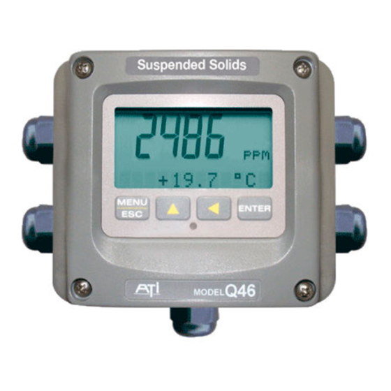
Suspended Solids Monitor
Home Office
Analytical Technology, Inc.
6 Iron Bridge Drive
Collegeville, PA 19426
Phone: 800-959-0299
610-917-0991
Fax:
610-917-0992
Email: sales@analyticaltechnology.com
O & M Manual
Model Q46/88
European Office
ATI (UK) Limited
Unit 1 & 2 Gatehead Business Park
Delph New Road, Delph
Saddleworth OL3 5DE
Phone: +44 (0)1457-873-318
Fax:
+ 44 (0)1457-874-468
Email: sales@atiuk.com
Advertisement
Table of Contents

Related Manuals for ATI Technologies Q46/88


Summary of Contents for ATI Technologies Q46/88
- Page 1 O & M Manual Model Q46/88 Suspended Solids Monitor Home Office European Office Analytical Technology, Inc. ATI (UK) Limited 6 Iron Bridge Drive Unit 1 & 2 Gatehead Business Park Collegeville, PA 19426 Delph New Road, Delph Phone: 800-959-0299 Saddleworth OL3 5DE...
-
Page 2: Table Of Contents
Standard System ......... 4 6.11 Cal Zero ......... 41 Features ..........6 6.12 Cal Span ........41 Q46/88 System Specifications ..... 7 Temperature Calibration ....42 Q46/88 Performance Specifications ..8 Check Signal Function ...... 43 6.31 Calibrate Check Signal ....43 PART 2 –... - Page 3 Table of Figures 1 - S ........................... 5 IGURE YSTEM PTIONS 2 – Q46 E ....................... 9 IGURE NCLOSURE IMENSIONS 3 - W ....................10 IGURE ALL OR IPE MOUNT BRACKET 4 - W ......................11 IGURE OUNTING IAGRAM 5 - P ......................
-
Page 4: Part 1 - Introduction
Profibus-DP, Modbus RTU or TCP/IP, or Ethernet-IP. Standard System Q46/88 systems include two components, the Q46 analyzer and an optical sensor with 30 ft. cable. Sensor mounting options include submersion, submersion with Auto-Clean holder, 1 ½” flow tee, or flowcell. If possible, the flowcell or flow tee should be used if expected suspended solids levels are always below 10 mg/l. -
Page 5: Figure 1 - System Options
Q46/88 Suspended Solids Monitor Part 1 - Introduction Figure 1 - System Options O&M Manual Rev-E (11/18) -
Page 6: Features
Q46/88 Suspended Solids Monitor Part 1 - Introduction Features Q46 electronic transmitters are designed to be a fully isolated instruments for operation from either 90-260 VAC or 12-24 VDC power supplies. Two 4-20 mA analog outputs are standard, and a third analog output is available as an option. -
Page 7: Q46/88 System Specifications
Q46/88 Suspended Solids Monitor Part 1 - Introduction Q46/88 System Specifications Displayed Parameters Main input, 0.1 mg/l to 10.00 g/l Sensor temperature, -5.0 to 50.0°C (23 to 122ºF) Loop current, 4.00 to 20.00 mA Sensor slope/offset Check Signal Level % Light Level... -
Page 8: Q46/88 Performance Specifications
Q46/88 Suspended Solids Monitor Part 1 - Introduction Altitude Up to 2000 m (6562 ft) Electrical Certification Ordinary Location, cCSAus (Certified to both CSA and UL standards), pollution degree 2, installation category 2 EMI/RFI Influence Designed to EN 61326-1 Weight 2.4 lb. -
Page 9: Part 2 - Analyzer Mounting
Part 2 – Analyzer Mounting General All Q46 Series instruments offer maximum mounting flexibility. A bracket is included with each unit that allows mounting to walls or pipes. Choose a location that is readily accessible for calibrations and keep in mind that it will be necessary to use solutions during the calibration process. -
Page 10: Wall Or Pipe Mount
Part 2 – Analyzer Mounting Q46/88 Suspended Solids Monitor Wall or Pipe Mount A PVC mounting bracket with attachment screws is supplied with each transmitter (see Figure 3 for dimensions). The multi-purpose bracket is attached to the rear of the enclosure using the four flat head screws. -
Page 11: Figure 4 - Wall Mounting Diagram
Part 2 – Analyzer Mounting Q46/88 Suspended Solids Monitor Figure 4 - Wall Mounting Diagram MENU ENTER Figure 5 - Pipe Mounting Diagram O&M Manual Rev-E (11/18) -
Page 12: Panel Mount, Ac Powered Monitor
Part 2 – Analyzer Mounting Q46/88 Suspended Solids Monitor Panel Mount, AC Powered Monitor Panel mounting of an AC powered monitor uses the panel mounting flange molded into the rear section of the enclosure. Figure 6 provides dimensions for the panel cutout required for mounting. The panel mounting bracket kit must be ordered separately (part number 05-0068). -
Page 13: Part 3 - Sensor Installation
Part 3 – Sensor Installation General The majority of suspended solids applications use a submersible sensor mounted on a pipe and submerged in aeration tanks, effluent channels, or other open tanks. For monitoring very low suspended solids levels, it is often better to use a flowcell or flow tee for measurement, which means the sample must be pumped to the measuring point. -
Page 14: Figure 8 - Submersible Sensor Assembly
Part 3 – Sensor Installation Q46/88 Suspended Solids Monitor Figure 8 - Submersible Sensor Assembly O&M Manual Rev-E (11/18) -
Page 15: In-Line Installation
Part 3 – Sensor Installation Q46/88 Suspended Solids Monitor In-Line Installation Suspended Solids sensors may be installed directly into a flowing pipe system provided that the water does not contain a lot of entrained air. A 1 ½” flow tee assembly is available for this purpose. -
Page 16: Figure 10 - Flow Tee Exploded View
Part 3 – Sensor Installation Q46/88 Suspended Solids Monitor Figure 10 - Flow Tee Exploded View O&M Manual Rev-E (11/18) -
Page 17: Flowcell Mounting
Part 3 – Sensor Installation Q46/88 Suspended Solids Monitor Flowcell Mounting Flowcells are used only for low suspended solids applications. The flowcell contains a needle valve for flow adjustment that can easily plug in high solids applications. I expected suspended solids will always be below 10 mg/l, the flowcell is a good choice. -
Page 18: Figure 12 - Sensor/Flowcell Exploded View
Part 3 – Sensor Installation Q46/88 Suspended Solids Monitor Figure 12 - Sensor/Flowcell Exploded View O&M Manual Rev-E (11/18) -
Page 19: Part 4 - Electrical Installation
Part 4 – Electrical Installation General The Q46 is powered in one of two ways, depending on the version purchased. The 12-24 VDC powered analyzer requires a customer supplied DC power supply. The 90-260 VAC version requires line power. Please verify the type of unit before connecting any power. WARNING: Do not connect AC line power to the DC version. - Page 20 Part 4 – Electrical Installation Q46/88 Suspended Solids Monitor WARNING Disconnect line power voltage BEFORE connecting line power wires to Terminal TB5 of the power supply. The power supply accepts only standard three-wire single phase power. The power supply is configured for 115 VAC or 230 VAC operation at the factory at time of order, and the power supply is labeled as such.
-
Page 21: Relay Connection
Part 4 – Electrical Installation Q46/88 Suspended Solids Monitor Relay Connection Three SPDT relays are provided on the power supply board. None of the relay contacts are powered. The user must supply the proper power to the contacts. For applications that require the same switched operating voltage as the Q46 (115 or 230 V), power may be jumped from the power input terminals at TB7. -
Page 22: Optional Output/Relay Connection
Part 4 – Electrical Installation Q46/88 Suspended Solids Monitor Optional Output/Relay Connection TB2 is used to connect the optional 3-relay card (Figure 154) OR the optional third analog output Out#3, (Figure 15). The Q46 can be configured for only one of these features, and the hardware for either option must be factory installed. -
Page 23: Direct Sensor Wiring
Part 4 – Electrical Installation Q46/88 Suspended Solids Monitor Direct Sensor Wiring Sensor connections are made to a terminal block mounted on the front section of the monitor. The sensor cable can be quickly connected to the Q46 terminal strip by matching the wire colors on the cable to the color designations on the label in the monitor. -
Page 24: Remote Sensor Wiring
Part 4 – Electrical Installation Q46/88 Suspended Solids Monitor Remote Sensor Wiring Generally it is best to keep the sensor close to the monitor. However, it is possible to mount the sensor as much as 100 feet from the monitor using a junction box and additional interconnect cable. -
Page 25: Part 5 - Configuration
Part 5 – Configuration User Interface The user interface for the Q46 Series instrument consists of a custom display and a membrane keypad. All functions are accessed from this user interface (no internal jumpers, pots, etc.). When power is first applied, you may notice that the display does not come on immediately. This is normal. -
Page 26: 5.11 Keys
Part 5 – Configuration Q46/88 Suspended Solids Monitor 5.11 Keys All user configurations occur through the use of four membrane keys. These keys are used as follows: MENU/ESC To scroll through the menu section headers or to escape from anywhere in software. -
Page 27: Software
Q46/88 Suspended Solids Monitor Part 5 - Configuration Icon Area The icon area contains display icons that assist the user in set-up and indicate important states of system functions. The CAL, CONFIG, and DIAG icons are used to tell the user what branch of the software tree the user is in while scrolling through the menu items. -
Page 28: Software Navigation
Q46/88 Suspended Solids Monitor Part 5 - Configuration 5.21 Software Navigation Within the CAL, CONFIG, CONTROL, and DIAG menu sections is a list of selectable items. Once a menu section (such as CONFIG) has been selected with the MENU key, the user can access the item list in this section by pressing either the ENTER key or the UP arrow key. -
Page 29: Figure 20 - Software Map
Q46/88 Suspended Solids Monitor Part 5 - Configuration Start MENU M ENU M ENU M ENU M ENU M ENU MEASURE CONFIG CONTROL DIAG SECTIONS (display only) ENTER ENTER ENTER ENTER Temperature PID 0% #1 Entry Lock Set Hold Cal Span... -
Page 30: Measure Menu [Measure]
Q46/88 Suspended Solids Monitor Part 5 - Configuration 5.22 Measure Menu [MEASURE] The default menu for the system is the display-only menu MEASURE. This menu is a display-only measurement menu, and has no changeable list items. When left alone, the instrument will automatically return to this menu after approximately 30 minutes. -
Page 31: Calibration Menu [Cal]
Q46/88 Suspended Solids Monitor Part 5 - Configuration Note: A display test (all segments ON) can be actuated by pressing and holding the ENTER key while viewing the model/version number on the lower line of the display. The MEASURE screens are intended to be used as a very quick means of looking up critical values during operation or troubleshooting. - Page 32 Q46/88 Suspended Solids Monitor Part 5 - Configuration sensor response is non-linear. Changing the table values is described later in this manual. Timer Func This function should be left in the OFF setting. It is used only for the Auto-Clean suspended solids system which is covered in another manual.
-
Page 33: Control Menu [Control]
Q46/88 Suspended Solids Monitor Part 5 - Configuration The AL setting allows two setpoints to be selected for the same relay, producing a HI-LO alarm band. In this mode, Relay A will trip inside or outside of the band, depending upon the Phase selected. See Figure 20 –... - Page 34 Q46/88 Suspended Solids Monitor Part 5 - Configuration PID Prop Proportional gain factor. The proportional gain value is a multiplier on [Iout1=PID] the controller error (difference between measured value and setpoint value.) Increasing this value will make the controller more responsive.
-
Page 35: Figure 21 - Control Relay Example, Hysteresis & Phase Options
Q46/88 Suspended Solids Monitor Part 5 - Configuration value will flash. Use arrow keys to modify value. Press ENTER to store the new value. *A Setpoint This function establishes the trip point for relay A. The entry value is limited to a value within the range specified in “Set Range”. Use the LEFT arrow key to select the first digit to be modified. -
Page 36: Figure 22 - Alarm Relay Example
Q46/88 Suspended Solids Monitor Part 5 - Configuration If Relay A Mode is set to Alarm Mode, AL, then the following settings will *Setpnt A-HI appear in the Config Menu list automatically. In this mode, two setpoints *Hyst A-HI can be selected on the same relay, to create an alarm band. Phase HI... -
Page 37: Diagnostics Menu [Diag]
Q46/88 Suspended Solids Monitor Part 5 - Configuration 5.26 Diagnostics Menu [DIAG] The diagnostics menu contains all of the user settings that are specific to the system diagnostic functions, as well as functions that aid in troubleshooting application problems. Set Hold The Set Hold function locks the current loop output values on the present process value and holds relays in current status. - Page 38 Q46/88 Suspended Solids Monitor Part 5 - Configuration Press ENTER to initiate user entry mode, and the entire value will flash. Use the UP arrow key to modify desired value; range of value is 0-9999 seconds. Press ENTER to store the new value.
- Page 39 Q46/88 Suspended Solids Monitor Part 5 - Configuration *Fail Out #3 OPTIONAL. This function sets the fail-mode of current loop output #3 under a FAIL condition. The settings and operation are identical to Fail Out for output #1. *Fail Val #3 OPTIONAL.
- Page 40 Q46/88 Suspended Solids Monitor Part 5 - Configuration Set Default The Set Default function allows the user to return the instrument back to factory default data for all user settings or for just the calibration default. It is intended to be used as a last resort troubleshooting procedure. All user settings or the calibration settings are returned to the original factory values.
-
Page 41: Part 6 - Calibration
4. Once the zero adjustment is complete, remove the filter from the incoming sample line. 6.12 Cal Span Calibration of a Q46/88 suspended solids monitor is normally done by adjusting the displayed value to a lab measurement. Lab measurements of suspended solids take quite a long time so often an estimated value is used. -
Page 42: Temperature Calibration
Q46/88 Suspended Solids Monitor Part 6 - Calibration value. Factory calibration is done using a formazin standard that may, or may not, have the same optical backscatter properties as the process in which the sensor is to be used. To set the span of the SS monitor, follow the procedure below. -
Page 43: Check Signal Function
Q46/88 Suspended Solids Monitor Part 6 - Calibration modify the value to the known ref solution temperature. Adjustments up to ± 5 °C from the factory calibrated temperature are allowed. Press ENTER. Once completed, the display will indicate PASS or FAIL. -
Page 44: External Light Function
This is possible when sensors are submerged in flowing streams outdoors in bright sunlight. While it is not normally an issue, the Q46/88 contains a sensor diagnostic feature that measures the amount of ambient light and can provide an alarm in the event that ambient light levels are too high for reliable operation. -
Page 45: Part 7 - System Maintenance
Part 7 – System Maintenance General The Q46/88 Suspended Solids Monitor will generally provide unattended operation over long periods of time. With proper care, the system should continue to provide measurements indefinitely. For reliable operation, maintenance on the system must be done on a regular schedule. -
Page 46: Part 8 - Troubleshooting
Part 8 – Troubleshooting General The information included in this section is intended to be used in an attempt to quickly resolve an operational problem with the system. During any troubleshooting process, it will save the most time if the operator can first determine if the problem is related to the analyzer, sensor, or some external source. -
Page 47: Analyzer Tests
Q46/88 Suspended Solids Monitor Part 8 - Troubleshooting Check for ground loops. Although the sensor is electrically isolated from the process water, high frequency sources of electrical noise may still cause erratic behavior in extreme conditions. If readings are very erratic after wiring has been checked, check for a possible AC ground loop by temporarily placing the sensor into a bucket of water. -
Page 48: 8.31 Display Messages
Q46/88 Suspended Solids Monitor Part 8 - Troubleshooting If analyzer does power up with a display, use the “Simulate” feature to check operation of the analog outputs (and relays contacts with a DVM.) Check sensor power circuits. With a DVM, verify between -4.5 and -5.5 VDC from sensor connection terminals WHITE (+) to BLACK (-). -
Page 49: Figure 23 - Display Messages
Q46/88 Suspended Solids Monitor Part 8 - Troubleshooting Cal Fail Failure of SS calibration. FAIL icon will not Clean sensor and redo span calibration. If still extinguish until successful calibration has been failure, sensor slope may be less than 80% or performed, or 30 minutes passes with no keys greater than 120%. -
Page 50: Part 9 - Pid Controller Details
Part 9 – PID Controller Q46/88 Suspended Solids Monitor Part 9 – PID Controller Details PID Description PID control, like many other control schemes, is used in chemical control to improve the efficiency of chemical addition or control. By properly tuning the control loop that controls chemical addition, only the amount of chemical that is truly required is added to the system, saving money. - Page 51 Part 7 – PID Controller Q46/88 Suspended Solids Monitor The most notable feature of the algorithm is the fact the proportional gain term affects all components directly (unlike some other algorithms - like the “series” form.) If a pre-existing controller utilizes the same form of the algorithm shown above, it is likely similar settings can for made if the units on the settings are exactly the same.
-
Page 52: Classical Pid Tuning
Part 7 – PID Controller Q46/88 Suspended Solids Monitor Classical PID Tuning Unlike many high speed position applications where PID loops are commonly used, the chemical feed application employed by this instrument does not require intense mathematical exercise to determine tuning parameters for the PID. In fact, the risk of instability is far greater with overly tuned PID control schemes. - Page 53 Part 7 – PID Controller Q46/88 Suspended Solids Monitor The easiest process’ to control with closed-loop schemes are generally linear, and symmetrical, in nature. For example, controlling level in tank where the opening of valve for a fixed period of time corresponds linearly to the amount that flows into a tank.
-
Page 54: Spare Parts
Spare Parts Part No. Description 07-0378 AC Powered monitor electronics assembly, 100-240 VAC 07-0379 DC Powered monitor electronics assembly 12-24 VDC 07-0380 AC Powered monitor electronics assembly w/Profibus, 100-240 VAC 07-0381 DC Powered monitor electronics assembly w/Profibus, 12-24 VDC 03-0445 Q46-88 Front Lid electronics assembly 03-0407 P/S Assy, 100-240 VAC... - Page 55 PRODUCT WARRANTY Analytical Technology, Inc. (Manufacturer) warrants to the Customer that if any part(s) of the Manufacturer's equipment proves to be defective in materials or workmanship within the earlier of 18 months of the date of shipment or 12 months of the date of start-up, such defective parts will be repaired or replaced free of charge.
- Page 56 WATER QUALITY MONITORS GAS DETECTION PRODUCTS Ammonia Dissolved Oxygen Carbon Monoxide Free Chlorine Hydrogen Nitric Oxide Combined Chlorine Oxygen Total Chlorine Cl2 Phosgene Residual Chlorine Dioxide Bromine Potassium Permanganate Chlorine Dissolved Ozone Chlorine Dioxide Fluorine pH/ORP Iodine Conductivity Acid Gases Hydrogen Peroxide O Ethylene Oxide Peracetic Acid...
Need help?
Do you have a question about the Q46/88 and is the answer not in the manual?
Questions and answers