Sign In
Upload
Download
Table of Contents
Contents
Add to my manuals
Delete from my manuals
Share
URL of this page:
HTML Link:
Bookmark this page
Add
Manual will be automatically added to "My Manuals"
Print this page
×
Bookmark added
×
Added to my manuals
Manuals
Brands
Tiger Manuals
Tractor Accessories
HEXA SERIES
Operator's manual and spare parts
Tiger HEXA SERIES Operator's Manual And Spare Parts
Disc plough
Hide thumbs
1
2
Table Of Contents
3
4
5
6
7
8
9
10
11
12
13
14
15
16
17
18
19
page
of
19
Go
/
19
Contents
Table of Contents
Troubleshooting
Bookmarks
Table of Contents
Table of Contents
1 Introduction
Areas of Usage
2 Description of the Machine
Expiry of Warranty
3 Warranty
4 Technical Specifications
Dimensions of Machine
Main Parts of Machine
5 Safety Measures
Follow General Safety Instructions
Follow Equipment Safety Instructions
Follow Operating Safety Instructions
Follow Maintenance Safety Instructions
Follow Transporting Safety Instructions
Follow Storage Safety Instructions
Safety Stickers on the Machine
6 Attaching of the Machine to the Tractor
Transporting of the Machine and the Stability of the Tractor and the Machine During Transport
Cutting Angle Adjustments
Tractor Stability and Lifting Capacity Check
7 Usage of Machine
Depth Adjustments
Guide Wheel Adjustment
8 Detach of the Machine from the Tractor
Leveling the Plough
Scrapper Adjustments
Width of Cut Adjustment
9 Maintenance
10 Trouble Shooting
11 Torque Table
Advertisement
Quick Links
Download this manual
Operator's Manual and Spare Parts
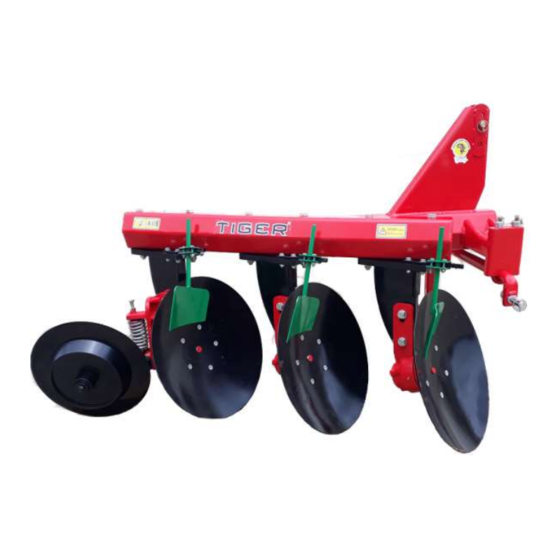
Disc Plough
MODEL –DH
HEXA SERIES
1
Table of
Contents
Previous
Page
Next
Page
1
2
3
4
5
Advertisement
Table of Contents
Need help?
Do you have a question about the HEXA SERIES and is the answer not in the manual?
Ask a question
Questions and answers
Related Manuals for Tiger HEXA SERIES
Tractor Accessories Tiger BENGAL JD6110-20M/R MY20 Mounting And Operating Instructions
Brute w/ independent hydraulics and bumper tank (223 pages)
Tractor Accessories Tiger BENGAL JD51 M Series Mounting And Operating Instructions
Boom w/ independent hydraulics and modular frame (240 pages)
Tractor Accessories Tiger BENGAL JD5 M T4F Series Mounting And Operating Instructions
Boom w/ independent hydraulics and modular frame (240 pages)
Tractor Accessories Tiger NH T6 145-55/CASE MXM 125 Mounting And Operating Instructions
Wildkat boom independent hydraulics (222 pages)
Tractor Accessories Tiger JD5075E T4F Mounting And Operating Instructions
Side flail w/ berm draft beam (176 pages)
Tractor Accessories Tiger JD5075E T4F Mounting And Operating Instructions
Side rotary (202 pages)
Tractor Accessories Tiger WILDKAT JD6105-20E T4F Manual
Rear stow side boom mower (238 pages)
Tractor Accessories Tiger JD5 M T4F Series Mounting And Operating Instructions
Side flail w/ independent hydraulics and modular frame (178 pages)
Tractor Accessories Tiger WILDKAT JD6105-25E T4F Manual
(240 pages)
Tractor Accessories Tiger JD6175R Mounting And Operating Instructions
Saber boom w/ independent hydraulics (236 pages)
Tractor Accessories Tiger BENGAL JD6110-30M/R T4F Mounting And Operating Instructions
(226 pages)
Tractor Accessories Tiger WILDKAT JD61 M/R Series Manual
(258 pages)
Tractor Accessories Tiger WILDCAT JD6105D Mounting And Operating Instructions
(252 pages)
Tractor Accessories Tiger BENGAL JD6 E T4F Series Mounting And Operating Instructions
(244 pages)
Tractor Accessories Tiger BENGAL 5085M Series Mounting And Operating Instructions
(294 pages)
This manual is also suitable for:
Dh
Table of Contents
Print
Rename the bookmark
Delete bookmark?
Delete from my manuals?
Login
Sign In
OR
Sign in with Facebook
Sign in with Google
Upload manual
Upload from disk
Upload from URL


Need help?
Do you have a question about the HEXA SERIES and is the answer not in the manual?
Questions and answers