Table of Contents
Advertisement
Advertisement
Table of Contents

Subscribe to Our Youtube Channel
Related Manuals for Honeywell Notifier IDR-2P


Summary of Contents for Honeywell Notifier IDR-2P
- Page 1 -2P, -2A & -6A repeaters user manual 997-411-000-9, Issue 9 March 2008...
- Page 2 IDR-2P, -2A & -6A Repeaters User Manual Quick Contents Reference by Section 997-411-000-9, Issue 9 March 2008...
-
Page 3: Table Of Contents
IDR-2P, -2A & -6A Repeaters User Manual Contents Introduction CE Marking System Design and Planning General Related Documents Warnings and Cautions Tips Installation Guide Pre-Installation Check List 2.1.1 Some DO’s and DON’T’s Transient Protection Installation 2.3.1 Checking Your Repeater for Damage 2.3.2 What to do if Your Repeater is Damaged or Suspect Installation Options... - Page 4 IDR-2P, -2A & -6A Repeaters User Manual 4.3.2 Power Diagnostics (-2A) 4.3.3 Pushbutton Test (-2A) 4.3.4 Edit NORMAL Message (-2A) 4.3.5 Restore NORMAL Message (-2A) 4.3.6 Language (-2A) 4.3.7 Mute Buzzer (-2P) 4.3.8 Cancel (-2A/-2P) Menus: -2A/-2P (ID50 Only) 4.4.1 Mute Buzzer (-2P) 4.4.2 LEDs/LCD/Buzzer Test (ID50 -2A/-2P) 25 4.4.3 Pushbutton Test (ID50 -2A) 4.4.4 Log (ID50 -2A/-2P)
-
Page 5: Introduction
IDR-2P, -2A & -6A Repeaters User Manual Introduction This manual provides the user with all necessary instructions for the installation, commissioning and operation of an IDR repeater. There are three variants of the IDR repeater: a. IDR-2P passive repeater, with a 2 line x 40 character LCD. -
Page 6: Ce Marking
IDR-2P, -2A & -6A Repeaters User Manual 1.1 CE Marking The repeater is CE-Marked to show that it conforms to the requirements of the following European Community Directives: Electromagnetic Compatibility Directive 89/ 336/EEC (and the amending Directives 92/31/EEC and 93/68/EEC). 1.2 System Design and Planning It is assumed that the system, of which the IDR repeater is a part, has been designed by... -
Page 7: Related Documents
IDR-2P, -2A & -6A Repeaters User Manual 1.4 Related Documents This manual only describes the IDR repeater. Refer to the documentation supplied with the fire control panel for information about that panel. 1.5 Warnings and Cautions Where appropriate, this manual includes You MUST connect a advisory warnings and cautions to remind you safety earth wire to the... -
Page 8: Installation Guide
IDR-2P, -2A & -6A Repeaters User Manual Installation Guide This Installation Guide provides simple guidelines on how to install an IDR repeater quickly and safely. 2.1 Pre-installation Check List Before installing the IDR repeater you must ensure that the following criteria have been met. -
Page 9: Transient Protection
IDR-2P, -2A & -6A Repeaters User Manual e. DO NOT locate the IDR repeater where there are high levels of vibration or shock. f. DO NOT site the IDR repeater where there would be restricted access to the internal equipment and cabling/wiring connections. 2.2 Transient Protection This equipment contains transient-protection devices. -
Page 10: Installation
IDR-2P, -2A & -6A Repeaters User Manual 2.3 Installation The IDR repeater is relatively simple to install providing the recommended procedures described in this Installation Guide are followed. Follow all installation instructions To avoid damage to the IDR described this manual. -
Page 11: What To Do If Your Repeater Is Damaged Or Suspect
IDR-2P, -2A & -6A Repeaters User Manual 2.3.2 What to do if Your Repeater is Damaged or Suspect If you have problems regarding the quality of any supplied order items including the IDR repeater or this manual, or items are missing, follow the procedure below: 1 DO NOT continue with the installation but contact your supplier for advice on what to... -
Page 12: Installation Options
IDR-2P, -2A & -6A Repeaters User Manual 2.4 Installation Options Installation of the IDR repeater is described in Section 2.5. The available options are described as follows: a. RS232 Board - Section 2.6. This allows Notifier-approved equipment to be connected to the IDR repeater. -
Page 13: Installing The Enclosure
IDR-2P, -2A & -6A Repeaters User Manual 2.5 Installing the Enclosure To ensure that the IDR repeater electronics remain clean and undamaged, it is recommended that the front door of the enclosure be covered before the enclosure is DO NOT use the fixed to the wall. -
Page 14: Fitting The Label Inserts
IDR-2P, -2A & -6A Repeaters User Manual 2.5.2 Fitting the Label Inserts With the IDR repeater door open and all power disconnected, fit the label inserts as follows: 1 a. IDR-2A used with ID50 panel only. Fold the IDR-2A pushbutton legends (345-429) at the perforated line. -
Page 15: Isolated Rs232 Board (Option)
IDR-2P, -2A & -6A Repeaters User Manual 2.6 Isolated RS232 Board (optional) This board is required only if Notifier-approved ATTENTION equipment is to be connected to the IDR repeater. Observe precautions for handling Electrostatic To fit the Isolated RS232 Board: Sensitive Devices 1 Use a hex key to open the IDR repeater door (A). -
Page 16: Bezel Kit (Option)
IDR-2P, -2A & -6A Repeaters User Manual 2.7 Bezel Kit (option) 1 & 4 The bezel is supplied with a dedicated back box which has fixing holes, three on the rear wall and two on each side wall. This procedure describes fixing using the rear wall fixing holes, although the procedure can be applied to the side fixing holes. -
Page 17: Installing The Wiring
IDR-2P, -2A & -6A Repeaters User Manual 2.8 Installing the Wiring 2.8.1 External Wiring Connections The following external wiring must be terminated at the Termination Board: a. 28V IN (18-32V dc) and 0V supply, from previous repeater, or from panel, or from external source. -
Page 18: Rs485 Serial Network - Address Switches And Termination Resistors
IDR-2P, -2A & -6A Repeaters User Manual 2.8.2 RS485 Serial Network - Address Switches and Termination Resistors The RS485 network is connected to the Each station address Termination Board as shown in Section 2.8.1. MUST be unique. No The following must be set during configuration: two stations may have the same address. -
Page 19: Id Net Network Via Rs232 - Address Switches
IDR-2P, -2A & -6A Repeaters User Manual 2.8.3 ID net Network via RS232 - Address Switches The ID net is connected by one of two methods as shown in the diagrams below. Connections to the Isolated RS232 Board are shown in Section 2.6. -
Page 20: Commissioning
IDR-2P, -2A & -6A Repeaters User Manual Commissioning This section gives the procedure for Only terminate the IDR commissioning the IDR repeater. repeater power cables at the fire control panel Commissioning consists of: after ALL preliminary checks have been done. a. -
Page 21: Powering The Repeater
IDR-2P, -2A & -6A Repeaters User Manual 3.2 Powering the Repeater The IDR repeater obtains 18-32V and 0V dc supplies either from the fire control panel auxiliary outputs or, depending upon the IDR repeater’s location, from a local independent power supply. Connections are made as described in Section 2.8.1. -
Page 22: Operation
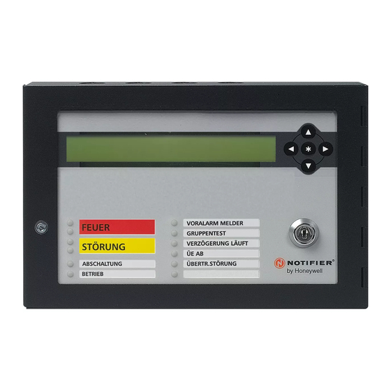
IDR-2P, -2A & -6A Repeaters User Manual Operation 4.1 Controls and Indicators IDR-2A repeater (2 x 40 display) IDR-2A repeater installed for other applications. installed for use with ID50 fire control panel IDR-2P is similar but without the following IDR-2P is similar but without the following pushbuttons or the keyswitch pushbuttons or the keyswitch PUSHBUTTONS (IDR-2A - ID50... - Page 23 IDR-2P, -2A & -6A Repeaters User Manual PUSHBUTTONS (IDR-6A) Silences repeater and panel buzzers (locally and across the network), and accepts an alarm. If any delays are active, first operation ends the delays, second operation sounds all sounders configured for Evacuate.
-
Page 24: Menus - General Information
IDR-2P, -2A & -6A Repeaters User Manual KEYPAD PUSHBUTTONS (IDR-2P, -2A, -6A) Used to move around the LCD menus. On ID50 repeaters only, is the Cancel pushbutton. Used to select repeater-specific menus (-2P, -2A) and to select various menu options, as defined on the menus (-2P, -2A, -6A). -
Page 25: Menus: -2A/-2P (Except Id50)
IDR-2P, -2A & -6A Repeaters User Manual 4.3 Menus: -2A/-2P (Except ID50) 4.3.1 Lamp Test (-2A) All pixels on the LCD are switched on and then off, the buzzer sounds intermittently, and the LEDs light sequentially in a continuous pattern from bottom right to top left. -
Page 26: Pushbutton Test (-2A)
IDR-2P, -2A & -6A Repeaters User Manual 4.3.3 Pushbutton Test (-2A) Press each pushbutton in turn. Verify that: a. The buzzer beeps. b. The LCD displays the name of the pushbutton. c. The corresponding LED as shown at the left illuminates. Turn the keyswitch to access level 1 to exit the test. -
Page 27: Edit Normal Message (-2A)
IDR-2P, -2A & -6A Repeaters User Manual 4.3.4 Edit NORMAL Message (-2A) This option lets you change the message that is displayed on the lower line of the LCD when the system status is normal. 1 Use the pushbuttons to select the character to be edited - it blinks. -
Page 28: Mute Buzzer (-2P)
IDR-2P, -2A & -6A Repeaters User Manual 4.3.7 Mute Buzzer (-2P) This silences the -2P IDR repeater’s internal buzzer. The LCD returns to the display prior to selection of Mute Buzzer. INTERNAL BUZZER IS SILENCED 4.3.8 Cancel (-2A/-2P) This option exits from the repeater-specific menus. -
Page 29: Leds/Lcd/Buzzer Test (Id50 -2A/-2P)
IDR-2P, -2A & -6A Repeaters User Manual 4.4.2 LEDs/LCD/Buzzer Test (ID50 -2A/ -2P) Note: This test is available for the -2P at access level 1; the -2A requires access level 2. All pixels on the LCD are switched on and then off, the buzzer sounds intermittently, and the LEDs light sequentially in a continuous pattern from bottom right to top left. -
Page 30: Edit Normal Message (Id50 -2A)
IDR-2P, -2A & -6A Repeaters User Manual 4.4.5 Edit NORMAL Message (ID50 -2A) This option lets you change the message that is displayed on the top line of the LCD when all systems are normal. 1 Use the pushbuttons to select the character to be edited - it blinks. -
Page 31: Menus: -6A
IDR-2P, -2A & -6A Repeaters User Manual 4.5 Menus: -6A Use the pushbutton to select the required menu option. 4.5.1 Test (-6A) 4.5.1.1 Lamp Test All pixels on the LCD are switched on and then off, the buzzer sounds intermittently, and the LEDs light sequentially in a continuous pattern from bottom right to top left. -
Page 32: Keypad Test
IDR-2P, -2A & -6A Repeaters User Manual 4.5.1.2 Keypad Test Press each repeater pushbutton in turn and verify that the corresponding square on the LCD becomes momentarily solid black. The example shows the test display when CHANGE TABS is operated. Turn the keyswitch counter-clockwise to exit the test and return to the display prior to test. -
Page 33: Display Event Log (-6A)
IDR-2P, -2A & -6A Repeaters User Manual 4.5.2 Display Event Log (-6A) Use the pushbuttons to scroll through the logged events by event number. Press the pushbutton to exit the log. The repeater returns to the display shown prior to entering the log. -
Page 34: Set Function
IDR-2P, -2A & -6A Repeaters User Manual 4.5.3.2 Set Function This option ensures that the IDR-6A repeats Configuration Menu: 1:Set Language the panel display in the correct manner. Set Function 3:Access Level for MUTE BUZZER Use the pushbuttons to select the 4:Silence/Resound pushbutton function required function (or cancel): User... -
Page 35: Silence/Resound Pushbutton Function
IDR-2P, -2A & -6A Repeaters User Manual 4.5.3.4 Silence/Resound Pushbutton Function By default, option 1 is selected. Option 2 is Configuration Menu: 1:Set Language only available if VdS (local or network zones) 2:Set Function is selected at the ‘Set Function’ menu. 3:Access Level for MUTE BUZZER Silence/Resound pushbutton function... -
Page 36: Disablement Led
IDR-2P, -2A & -6A Repeaters User Manual 4.5.3.7 Disablement LED The panel has a general Disablement LED which is configured, by default, to illuminate with the DELAY ACTIVE LED when a delay is active. The repeater’s general Disablement LED can be configured to not illuminate during active EN54-2: 9.2 delays. -
Page 37: Appendix 1 - Specification
IDR-2P, -2A & -6A Repeaters User Manual Appendix 1 - Specification Mechanical Construction: Mild steel sheet enclosure. All displays and controls are carried on the enclosure door. Dimensions (mm): 165.0(h) x 253.5(w) x 50.0(d) Weight: 1.7kg approx. Fixing: Three mounting holes in enclosure Cable Entry: 4 x 20mm knockouts in top of enclosure 3 x 20mm knockouts in back of enclosure... - Page 38 IDR-2P, -2A & -6A Repeaters User Manual RS232 Serial Port - Temporary PC connection Baud rate: 9600 Baud Connector: D-type on Control Board Max cable length: RS232 Isolated Serial Port (Optional) - Notifier-approved Equipment Isolation: Functional at 42V Baud rate: 9600 Baud Connector: Terminal block on RS232 Board...
-
Page 39: Appendix 2 - Battery Calculations
IDR-2P, -2A & -6A Repeaters User Manual Appendix 2 - Battery Calculations During the quiescent period it is reasonable to assume that the minimum voltage from the battery will be 24V for the vast majority of the time. On this premise the 24V supply figure can be used for all systems during this period. -
Page 40: Appendix 3 - Idr-6A Repeater Limitations A3
IDR-2P, -2A & -6A Repeaters User Manual Appendix 3 - IDR-6A Repeater Limitations Limitation Applicability of the limitation Repeater is on Repeater is on Repeater and RS232, panels RS485 to local panels are on are on ID panel, panels Master/Slave are on ID Alarm Outputs Disablements If ‘Alarm Outputs by Zone’... - Page 41 Charles Avenue T: +44 (0) 1444 230 300 Burgess Hill F: +44 (0) 1444 230 888 W. Sussex RH15 9UF sales@notifierfiresystems.co.uk www.notifierfiresystems.co.uk local distributor Quality Systems Certificate No. 154 Assessed to ISO9001 Every care has been taken in the preparation of this document but no liability can be accepted for the use of the information therein. Design features may be changed or amended without prior notice.
Need help?
Do you have a question about the Notifier IDR-2P and is the answer not in the manual?
Questions and answers