Table of Contents
Advertisement
Quick Links
This user guide describes the characteristics, operation, and the use of the DAC8580/81 Evaluation
Module. It covers all pertinent areas involved to properly use this EVM board along with the devices that it
supports. The physical printed circuit board (PCB) layout, schematic diagram and circuit descriptions are
included.
1
2
3
4
5
1
2
3
4
5
6
7
8
9
10
11
12
13
14
15
16
1
2
3
4
5
6
7
8
Microsoft, Windows are registered trademarks of Microsoft Corporation.
All other trademarks are the property of their respective owners.
SLAU173A - December 2005 - Revised November 2009
Submit Documentation Feedback
...............................................................................................................
............................................................................................
..............................................................................................................
.....................................................................................
.............................................................................................................
.........................................................................................
...............................................................................................................
................................................................................................
....................................................................................................
.....................................................................................................
............................................................................................
...........................................................................................................
................................................................................
...............................................................................
...................................................................................
...................................................................................
...................................................................................................
....................................................................................
................................................................................
.............................................................................................
.....................................................................................
...................................................................................
..................................................................................................
...........................................................................................
..................................................................................................
......................................................................................
Copyright © 2005-2009, Texas Instruments Incorporated
SLAU173A - December 2005 - Revised November 2009
DAC8580/81 Evaluation Module
Contents
List of Figures
.............................................
List of Tables
.....................................................................
............................................................
User's Guide
DAC8580/81 Evaluation Module
2
3
8
13
17
3
4
5
5
6
6
6
7
7
9
9
11
14
15
16
17
8
10
10
10
11
16
17
17
1
Advertisement
Table of Contents

Related Manuals for Texas Instruments DAC8580


Summary of Contents for Texas Instruments DAC8580
-
Page 1: Table Of Contents
SLAU173A – December 2005 – Revised November 2009 DAC8580/81 Evaluation Module This user guide describes the characteristics, operation, and the use of the DAC8580/81 Evaluation Module. It covers all pertinent areas involved to properly use this EVM board along with the devices that it supports. -
Page 2: Evm Overview
DAC8580/81EVM is used throughout this document. Features This EVM features the DAC8580/81 digital-to-analog converter (DAC). It provides a quick and easy way to evaluate the functionality and performance of the high-resolution, serial input DAC. The EVM provides the serial interface header to easily attach to any host microprocessor or TI DSP-based system for communication. -
Page 3: Pcb Design And Performance
TI DSP, or some sort of a signal/waveform generator. The headers J2 (top side) and P2 (bottom side) are pass-through connectors provided to allow the control signals and data required to interface a host processor or waveform generator to the DAC8580/81EVM using a custom-built cable. -
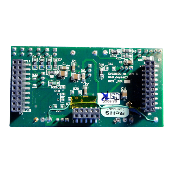
Page 4: Top Silkscreen
Figure The DAC8580/81EVM board is constructed on a four-layer printed-circuit board (PCB) using a copper-clad FR-4 laminate material. The PCB has a dimension of 43,1800 mm (1.7000 inch) × 82,5500 mm (3.2000 inch), and the board thickness is 1,5748 mm (0.0620 inch). -
Page 5: Layer 1 (Top Signal Plane)
PCB Design and Performance www.ti.com Figure 4. Layer 2 (Ground Plane) Figure 5. Layer 3 (Power Plane) SLAU173A – December 2005 – Revised November 2009 DAC8580/81 Evaluation Module Submit Documentation Feedback Copyright © 2005–2009, Texas Instruments Incorporated... -
Page 6: Layer 3 (Power Plane)
Figure 7. Bottom Silkscreen EVM Performance Results The EVM performance test was achieved using the DAC8580/81EVM piggy-backed onto the High Interface Board (HIB) for DAC tester, and tested using the Teradyne A580 connected to a personal computer. The EVM board is tested for all codes of the device under test (DUT) and is allowed to settle before the measurement is recorded. -
Page 7: Inl Characteristic Plot For The Dac8581
PCB Design and Performance www.ti.com The results of the DAC8580/81EVM characterization test are shown in Figure 8 Figure Figure 8. INL Characteristic Plot for the DAC8581 Figure 9. DNL Characteristic Plot for the DAC8581 SLAU173A – December 2005 – Revised November 2009... -
Page 8: Evm Operation
This section covers in detail the EVM operation to provide guidance to the user in evaluating the onboard DAC and how to interface the EVM to a host processor. See the specific DAC data sheet, as listed in the Related Documentation from Texas Instruments section (Section 3.5) of this user guide for more information about the DAC serial interface and other related... -
Page 9: Dac8580Evm Default Jumper Setting
This DAC EVM interfaces with any host processor capable of handling serial communication protocols or the popular TI DSP. For more information regarding the serial interface of the particular DAC installed, see the specific DAC data sheet, as listed in the Related Documentation from Texas Instruments section of this user guide. -
Page 10: Unity Gain Output Jumper Settings
, to the negative rail of operational amplifier, U2, for bipolar supply mode, or ties it to AGND for unipolar supply mode. DAC8580/81 Evaluation Module SLAU173A – December 2005 – Revised November 2009 Submit Documentation Feedback Copyright © 2005–2009, Texas Instruments Incorporated... -
Page 11: Dac Output Waveform
Negative supply rail of the output operational amplifier, U2, is powered by V for bipolar operation. Negative supply rail of the output operational amplifier, U2, is tied to AGND for unipolar operation. SLAU173A – December 2005 – Revised November 2009 DAC8580/81 Evaluation Module Submit Documentation Feedback Copyright © 2005–2009, Texas Instruments Incorporated... - Page 12 Disconnect the MUTEB/CLR pin of the DAC8580/DAC8581 from AGND and configure it for normal operation. Connect the MUTEB/CLR pin of the DAC8580/DAC8581 to AGND and set the DAC output to midscale (~0V). Should not be installed for proper operation of the DAC8581EVM.
-
Page 13: Using The Dac8581Evm With Dxp
Related Documentation From Texas Instruments To obtain a copy of any of the following TI documents, call the Texas Instruments Literature Response Center at (800) 477–8924 or the Product Information Center (PIC) at (972) 644–5580. When ordering, identify the manual by its title and literature number. Updated documents can also be obtained through the TI Web site at www.ti.com. -
Page 14: Mmb0 With Dac8581Evm Installed
When using external power supplies applied to J14 on the MMB0, please ensure all shorting blocks from J13 are completely removed. Permanent damage to the MMB0 may occur otherwise. DAC8580/81 Evaluation Module SLAU173A – December 2005 – Revised November 2009 Submit Documentation Feedback Copyright © 2005–2009, Texas Instruments Incorporated... -
Page 15: Loading A Dac8581Evm Configuration
Figure 14 illustrates. Choose the DAC configuration file for the device installed on the EVM. Figure 14. Loading a DAC8581EVM Configuration SLAU173A – December 2005 – Revised November 2009 DAC8580/81 Evaluation Module Submit Documentation Feedback Copyright © 2005–2009, Texas Instruments Incorporated... -
Page 16: Dac8581Evm: Frequency/Amplitude And Update Rate Adjustments
The device is in normal operating mode. To use this function, ensure that no jumpers are placed on W16 or J2 pin 14. DAC8580/81 Evaluation Module SLAU173A – December 2005 – Revised November 2009 Submit Documentation Feedback Copyright © 2005–2009, Texas Instruments Incorporated... -
Page 17: Bill Of Materials
U4 can be substituted for U3 for external reference source. The DUT installed, U1, for the EVM, is either a DAC8580 or DAC8581 device. For the DAC8581, the following parts are not installed in addition to the preceding listing: R1, R2, R3, R4, R25, R28, R38, R39, W7, W8, W9 W10, and W17. - Page 18 Bill of Materials www.ti.com Table 8. DAC8580/81EVM Bill of Materials (continued) Item Value Designators Description Vendor Vendor Part Number 10 μF C5 C6 C11 Multilayer Ceramic Chip Capacitor, 1210 C3225X7R1E106KT SMD, 25V, ±15% TC, ±10% Tol 20 kΩ 1/8W 1206 Thick Film Chip Resistor, ±1%...
- Page 19 Bill of Materials www.ti.com Table 8. DAC8580/81EVM Bill of Materials (continued) Item Value Designators Description Vendor Vendor Part Number 4 × 1 × 0.1 TH Modified 0.025" Square Post Header Samtec MTSW-104-08-T-S-295 4.096 V Voltage SOT23-3, 4.096 V Precision Voltage...
- Page 20 DVDD = +2.7V to +5.0V Digital AVSS = -5V Analog 12500 TI Boulevard. Dallas, Texas 75243 VCC = +15V Title: VSS = -15V DAC8580_81 EVM Engineer: J. PARGUIAN DOCUMENTCONTROL # 6464408 REV: Drawn By: FILE: DATE: SIZE: 12-Oct-2005 SHEET: DAC8580 RevA.Sch...
- Page 21 Evaluation Board/Kit Important Notice Texas Instruments (TI) provides the enclosed product(s) under the following conditions: This evaluation board/kit is intended for use for ENGINEERING DEVELOPMENT, DEMONSTRATION, OR EVALUATION PURPOSES ONLY and is not considered by TI to be a finished end-product fit for general consumer use. Persons handling the product(s) must have electronics training and observe good engineering practice standards.
- Page 22 IMPORTANT NOTICE Texas Instruments Incorporated and its subsidiaries (TI) reserve the right to make corrections, modifications, enhancements, improvements, and other changes to its products and services at any time and to discontinue any product or service without notice. Customers should obtain the latest relevant information before placing orders and should verify that such information is current and complete.
- Page 23 Mouser Electronics Authorized Distributor Click to View Pricing, Inventory, Delivery & Lifecycle Information: Texas Instruments DAC8581EVM...
Need help?
Do you have a question about the DAC8580 and is the answer not in the manual?
Questions and answers