Table of Contents
Advertisement
Quick Links
www.ti.com
EVM User's Guide: DP83826-EVM-AM2
AM2x Evaluation Module for Industrial Ethernet PHY Add-
on Board
Description
DP83826-EVM-AM2 is an Industrial Ethernet PHY
add-on board to be used with AM2x series Sitara
high-performance microcontroller evaluation modules.
This add-on board is an excellent choice for initial
Ethernet evaluation and prototyping using AM2x
EVMs. DP83826-EVM-AM2 is equipped with a TI
DP83826 low latency 10/100-Mbps PHY with MII
interface and enhanced mode, and a standard RJ45
Ethernet networking connector. DP83826-EVM-AM2
is currently supported on
AM263Px MCU PLUS
SDK.
SPRUJA8 – JANUARY 2024
Submit Document Feedback
™
TMDSCNCD263P
and the
Copyright © 2024 Texas Instruments Incorporated
Features
The Sitara™ AM2x EVM Industrial Ethernet PHY Add-
on Board has the following features:
•
DP83826
low latency 10/100-Mbps Industrial
Ethernet PHY with MII interface and enhanced
mode
•
Standard RJ45 Ethernet networking connector
•
Shielded DF40GB 48-pin connector for interfacing
with Sitara
™
AM2x series evaluation modules
AM2x Evaluation Module for Industrial Ethernet PHY Add-on Board
Description
1
Advertisement
Table of Contents

Subscribe to Our Youtube Channel
Related Manuals for Texas Instruments DP83826-EVM-AM2


Summary of Contents for Texas Instruments DP83826-EVM-AM2
- Page 1 This add-on board is an excellent choice for initial Ethernet PHY with MII interface and enhanced Ethernet evaluation and prototyping using AM2x mode EVMs. DP83826-EVM-AM2 is equipped with a TI • Standard RJ45 Ethernet networking connector DP83826 low latency 10/100-Mbps PHY with MII •...
-
Page 2: Kit Contents
• Sitara AM2x EVM Note DP83826-EVM-AM2 can be available as a virtual bundle with select Sitara AM2x EVMs. Visit the EVM product page (DP83826-EVM-AM2) for more information. 1.3 Device Information The DP83826 offers low and deterministic latency, low power and supports 10BASE-Te, 100BASE-TX Ethernet protocols to meet stringent requirements in real-time industrial Ethernet systems. -
Page 3: Ethernet Connector
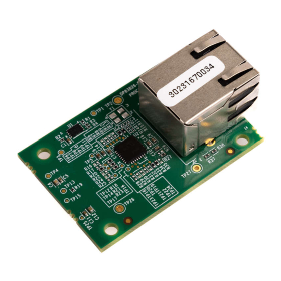
2.1 Component Identification 512Kb EEPROM RJ45 Ethernet Connector DP83826 Industrial Ethernet PHY Figure 2-1. DP83826-EVM-AM2 Top Side DF40GB 48-pin shielded connector Figure 2-2. DP83826-EVM-AM2 Bottom Side SPRUJA8 – JANUARY 2024 AM2x Evaluation Module for Industrial Ethernet PHY Add-on Board Submit Document Feedback... -
Page 4: Power Requirements
2.2.1 Power Tree The DP83826-EVM-AM2 power is supplied from the main Sitara AM2x EVM via the DF40GB connector. 3.3V (VDDIO) is connected to pin 44 and 46 on the DF40GB connector, and is passed to the source inputs on the DP83826ERHBT Industrial Ethernet PHY through a pair of ferrite beads (one per supply net). - Page 5 Hardware 2.3 Functional Block Diagram Figure 2-4. AM2x Industrial Ethernet PHY Add-on Board Block Diagram SPRUJA8 – JANUARY 2024 AM2x Evaluation Module for Industrial Ethernet PHY Add-on Board Submit Document Feedback Copyright © 2024 Texas Instruments Incorporated...
-
Page 6: Header Information
Hardware www.ti.com 2.4 Header Information The DP83826-EVM-AM2 is equipped with a Hirose DF40GB 2x24-pin connector (J2) to connect to Sitara AM2x EVMs. Listed below are the features of this connector relevant to this EVM: • 2x24 pins • Shielded type to support high-speed signals and prevent noise •... -
Page 7: Test Points
Hardware 2.5 Test Points DP83826-EVM-AM2 is equipped with multiple test points for hardware debug and bench testing. Table 2-2 shows the test points on the board and their associated signal net. Table 2-2. DP83826-EVM-AM2 Test Points Test Point Signal... - Page 8 The MDIO and Interrupt signals from the main EVM SoC to the PHY require 2.2KΩ pull up resistors to the I/O supply voltage for proper operation. These resistors are not assembled by default on the DP83826-EVM-AM2, but there are footprints if the main EVM does not have these signals pulled up. The interrupt signal is driven by a GPIO signal that is mapped from the main EVM SoC.
- Page 9 MDIX enable RX_D0 auto-negotiation enable RX_DV RX_ER LED1 on PHY Pin 31 CLKOUT/LED1 Odd nibble detection enabled SPRUJA8 – JANUARY 2024 AM2x Evaluation Module for Industrial Ethernet PHY Add-on Board Submit Document Feedback Copyright © 2024 Texas Instruments Incorporated...
-
Page 10: Integration Guide
Figure 2-8 shows the side profile of the PCB. Figure 2-8. Industrial Ethernet PHY Add-on Board Side Profile AM2x Evaluation Module for Industrial Ethernet PHY Add-on Board SPRUJA8 – JANUARY 2024 Submit Document Feedback Copyright © 2024 Texas Instruments Incorporated... - Page 11 Figure 2-9. DF40GB Connector Mounting Position 2.7.3 Mounting Holes The DP83826-EVM-AM2 is designed with mounting holes to securely attach to the main Sitara AM2x MCU EVM. The compatible Sitara AM2x EVMs are designed to have matching mounting holes for an Ethernet Add-on Board to connect to.
-
Page 12: Rj-45 Ethernet Connector
2.7.4 RJ45 Ethernet Connector The DP83826-EVM-AM2 has an RJ45 Ethernet Connector for sending and receiving signals from the DP83826 Ethernet PHY. Different Industrial Ethernet PHYs utilize the same connector, and must be used on custom Industrial Ethernet PHY Add-on Boards. -
Page 13: Additional Information
5.2 Compatible Sitara™ MCU AM2x EVMs This Ethernet add-on board is compatible with the following EVMs: • TMDSCNCD263P SPRUJA8 – JANUARY 2024 AM2x Evaluation Module for Industrial Ethernet PHY Add-on Board Submit Document Feedback Copyright © 2024 Texas Instruments Incorporated... - Page 14 STANDARD TERMS FOR EVALUATION MODULES Delivery: TI delivers TI evaluation boards, kits, or modules, including any accompanying demonstration software, components, and/or documentation which may be provided together or separately (collectively, an “EVM” or “EVMs”) to the User (“User”) in accordance with the terms set forth herein.
- Page 15 www.ti.com Regulatory Notices: 3.1 United States 3.1.1 Notice applicable to EVMs not FCC-Approved: FCC NOTICE: This kit is designed to allow product developers to evaluate electronic components, circuitry, or software associated with the kit to determine whether to incorporate such items in a finished product and software developers to write software applications for use with the end product.
- Page 16 www.ti.com Concernant les EVMs avec antennes détachables Conformément à la réglementation d'Industrie Canada, le présent émetteur radio peut fonctionner avec une antenne d'un type et d'un gain maximal (ou inférieur) approuvé pour l'émetteur par Industrie Canada. Dans le but de réduire les risques de brouillage radioélectrique à...
- Page 17 www.ti.com EVM Use Restrictions and Warnings: 4.1 EVMS ARE NOT FOR USE IN FUNCTIONAL SAFETY AND/OR SAFETY CRITICAL EVALUATIONS, INCLUDING BUT NOT LIMITED TO EVALUATIONS OF LIFE SUPPORT APPLICATIONS. 4.2 User must read and apply the user guide and other available documentation provided by TI regarding the EVM prior to handling or using the EVM, including without limitation any warning or restriction notices.
- Page 18 Notwithstanding the foregoing, any judgment may be enforced in any United States or foreign court, and TI may seek injunctive relief in any United States or foreign court. Mailing Address: Texas Instruments, Post Office Box 655303, Dallas, Texas 75265 Copyright © 2023, Texas Instruments Incorporated...
-
Page 19: Important Notice
TI products. TI’s provision of these resources does not expand or otherwise alter TI’s applicable warranties or warranty disclaimers for TI products. TI objects to and rejects any additional or different terms you may have proposed. IMPORTANT NOTICE Mailing Address: Texas Instruments, Post Office Box 655303, Dallas, Texas 75265 Copyright © 2024, Texas Instruments Incorporated...
Need help?
Do you have a question about the DP83826-EVM-AM2 and is the answer not in the manual?
Questions and answers