Table of Contents
Advertisement
Quick Links
This user's guide provides complete details of the customer evaluation module (EVM) for the DRV10987
device including hardware implementation, jumper configuration, and operating procedure to run 3-phase
BLDC motors. This EVM user's guide is intended to be used with the
optimally tune a user motor.
1
...................................................................................................................
2
3
3.1
3.2
3.3
3.4
3.5
3.6
4
4.1
4.2
5
6
7
7.1
7.2
1
2
3
4
5
6
7
8
9
10
11
12
13
14
15
16
17
SLOU476 - August 2017
Submit Documentation Feedback
DRV10987 Evaluation Module User's Guide
..............................................................................................
.....................................................................................................
.................................................................................
...........................................................................................
.......................................................................................
..............................................................................................
..........................................................................................
..........................................................................................................
..............................................................................................................
.............................................................................................................
.......................................................................................................
........................................................................................
...........................................................................................
..........................................................................................................
............................................................................................
...................................................................................
List of Figures
.............................................................................................................
............................................................................................
..................................................................................................
..........................................................................................................
...........................................................................................................
.......................................................................................
..........................................................................................
..........................................................................................................
..........................................................................................................
........................................................................................................
...........................................................................................................
....................................................................................................
.....................................................................................
.........................................................................................................
.....................................................................................................
..............................................................................................
Copyright © 2017, Texas Instruments Incorporated
Contents
....................................................
.................................................................
.................................................................
DRV10987 Evaluation Module User's Guide
User's Guide
SLOU476 - August 2017
DRV10987 Tuning Guide
to
3
3
4
4
4
4
5
5
5
6
6
6
10
15
15
15
17
18
36
3
6
7
7
7
8
9
10
11
11
12
13
14
15
16
18
19
1
Advertisement
Table of Contents

Related Manuals for Texas Instruments DRV10987 EVM


Summary of Contents for Texas Instruments DRV10987 EVM
-
Page 1: Table Of Contents
Fault Code Information ..................Disabled Motor Operation Selected ......................OverRide Selected ..................... DRV10987 Schematic ..............Setup_DRV109xx_EVM.exe from the Volume Folder ....................GUI Installation Initialization SLOU476 – August 2017 DRV10987 Evaluation Module User's Guide Submit Documentation Feedback Copyright © 2017, Texas Instruments Incorporated... - Page 2 ....................DRV10987 Bill of Materials ................GUI to DRV10987 Register Cross Reference Trademarks All trademarks are the property of their respective owners. DRV10987 Evaluation Module User's Guide SLOU476 – August 2017 Submit Documentation Feedback Copyright © 2017, Texas Instruments Incorporated...
-
Page 3: Drv10987 Evm Kit Contents
10-pin ribbon cable to connect the USB2ANY and DRV10987 EVM • DRV10987 EVM GUI The DRV10987 EVM boards and GUI are designed to work together to evaluate the device features. Introduction The DRV10987 EVM is a complete solution for evaluating the DRV10987 12-V or 24-V, three-phase sensorless BLDC motor drivers. -
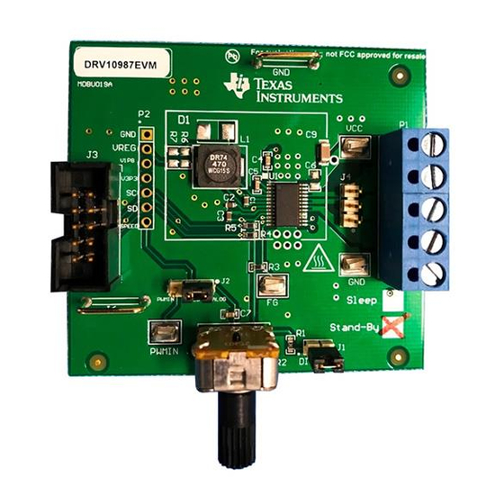
Page 4: Drv10987 Evm Board
DRV10987 EVM Board Power and Motor Connectors P1 The DRV10987 EVM shares terminal P1 for power supply and motor-phase output. Use a single power- supply rail between 6.2 V to 28 V to operate the EVM. Table 1 lists the pin assignment of terminal P1. -
Page 5: Jumper J1 (Direction)
Jumper J1 (Direction) To control the spin direction of the motor, the DRV10987 EVM is equipped with a direction jumper. Depending if 3V3 or GND is supplied to the DRV10987 direction input, the motor spins either in forward or reverse direction. -
Page 6: Drv10987 Gui
DRV10987 GUI www.ti.com DRV10987 GUI Overview The DRV10987 EVM is provided with a GUI to configure the device and tune the application. See Appendix A for instructions to download and install the application. The GUI is structured into three tabs (Basic Settings, Advanced Settings, and Display) allowing configuration of the register settings and tuning of the device parameters for the target application. -
Page 7: Example Dropdown Menu
To program the DRV10987 devices and change the default EEPROM settings, follow the instructions listed in the DRV10987 12- to 24-V, Three-Phase, Sensorless BLDC Motor Driver data sheet. SLOU476 – August 2017 DRV10987 Evaluation Module User's Guide Submit Documentation Feedback Copyright © 2017, Texas Instruments Incorporated... -
Page 8: Drv10987 Gui Advanced Settings
PWM frequency, Current Limit for Lock Detection, slew rate, Duty Cycle Limit, spread-spectrum modulation, and Temp Warning Action. Figure 6. DRV10987 GUI Advanced Settings DRV10987 Evaluation Module User's Guide SLOU476 – August 2017 Submit Documentation Feedback Copyright © 2017, Texas Instruments Incorporated... -
Page 9: Drv10987 Gui Display Settings
To control the motor speed using the GUI, check the OverRide bit and set the motor speed from 0 to 511 decimal. To disable Motor Operation, check the Disable Motor Operation bit. Figure 7. DRV10987 GUI Display Settings SLOU476 – August 2017 DRV10987 Evaluation Module User's Guide Submit Documentation Feedback Copyright © 2017, Texas Instruments Incorporated... -
Page 10: Out-Of-The-Box Quick-Start Guide
Step 10. Click the OK button. Figure 8. Initial GUI Screen • If no hardware is connected, or if a hardware connection problem occurs, the GUI DRV10987 Evaluation Module User's Guide SLOU476 – August 2017 Submit Documentation Feedback Copyright © 2017, Texas Instruments Incorporated... -
Page 11: Initial Gui Screen
GUI is communicating with the device. Click the Enable Configure to change this button from the red to green (see Figure 11). SLOU476 – August 2017 DRV10987 Evaluation Module User's Guide Submit Documentation Feedback Copyright © 2017, Texas Instruments Incorporated... -
Page 12: Enable Configure
CAUTION Do not short motor phases to VCC at connector P1, specifically P1-2 (Wphase) to P1-1(VCC) because EVM is in power-on condition. DRV10987 Evaluation Module User's Guide SLOU476 – August 2017 Submit Documentation Feedback Copyright © 2017, Texas Instruments Incorporated... -
Page 13: Fault Code Information
Sleep mode device, check the Disable Motor Operation bit, connect the motor phases of the user motor to connector P1, load, or change desired parameter information, then uncheck the Disable Motor Operation bit. SLOU476 – August 2017 DRV10987 Evaluation Module User's Guide Submit Documentation Feedback Copyright © 2017, Texas Instruments Incorporated... -
Page 14: Disabled Motor Operation Selected
Step 13. Change the motor direction by connecting or removing jumper J1. Step 14. Switch to the Display tab and select the OverRide checkbox to override the PWM speed control. DRV10987 Evaluation Module User's Guide SLOU476 – August 2017 Submit Documentation Feedback Copyright © 2017, Texas Instruments Incorporated... -
Page 15: Power-On Sequence And Connection With User Specific Motor
Schematic and Bill of Materials This section contains the DRV10987 schematic and bill of materials (BOM). Schematic Figure 15 shows the DRV10987 schematic. SLOU476 – August 2017 DRV10987 Evaluation Module User's Guide Submit Documentation Feedback Copyright © 2017, Texas Instruments Incorporated... -
Page 16: Drv10987 Schematic
V3P3 25k ohm PWMIN SPEED 0.1µF Analog Digital Speed Control Direction Control Copyright © 2016, Texas Instruments Incorporated Figure 15. DRV10987 Schematic DRV10987 Evaluation Module User's Guide SLOU476 – August 2017 Submit Documentation Feedback Copyright © 2017, Texas Instruments Incorporated... -
Page 17: Bill Of Materials (Bom)
Schematic and Bill of Materials www.ti.com Bill of Materials (BOM) Table 6 lists the DRV10987 EVM bill of materials. Table 6. DRV10987 Bill of Materials Designator Description Manufacturer Part Number Quantity !PCB Printed Circuit Board DRV10987 CAP, CERM, 10uF, 10V, +/-20%, X5R, 0603... -
Page 18: Appendix Agui Installation And Overview
2.7, USB2ANY SDK along with the GUI installation. 1. Double click on the Setup_DRV109xx_EVM.exe from the DRV109xx folder as shown in Figure Figure 16. Setup_DRV109xx_EVM.exe from the Volume Folder GUI Installation and Overview SLOU476 – August 2017 Submit Documentation Feedback Copyright © 2017, Texas Instruments Incorporated... -
Page 19: Gui Installation Initialization
I accept the agreement radio button and then click the Next > button to proceed to the next step. Figure 18. License Agreement SLOU476 – August 2017 GUI Installation and Overview Submit Documentation Feedback Copyright © 2017, Texas Instruments Incorporated... -
Page 20: Gui Destination Directory
5. The Ready to Install window appears next as shown in Figure 20. Click the Next > to begin installation. Figure 20. GUI Start Installation GUI Installation and Overview SLOU476 – August 2017 Submit Documentation Feedback Copyright © 2017, Texas Instruments Incorporated... -
Page 21: Gui Installation In Progress
7. After the installation of the GUI, the Python installation initiates. When Python is installed, a the window shown in Figure 22 is displayed. Click the Finish button to proceed with the USB2ANY installation. Figure 22. Python Installation Complete SLOU476 – August 2017 GUI Installation and Overview Submit Documentation Feedback Copyright © 2017, Texas Instruments Incorporated... -
Page 22: Usb2Any Installation Initialization
I accept the agreement radio button and then click the Next > button to proceed. Figure 24. USB2ANY License Agreement GUI Installation and Overview SLOU476 – August 2017 Submit Documentation Feedback Copyright © 2017, Texas Instruments Incorporated... -
Page 23: Usb2Any Destination Directory
11. The Ready to Install window is displayed next as shown in Figure 26. Click the Install button to begin the USB2ANY installation. Figure 26. USB2ANY Start Installation SLOU476 – August 2017 GUI Installation and Overview Submit Documentation Feedback Copyright © 2017, Texas Instruments Incorporated... -
Page 24: Usb2Any Installation Complete
DRV10975 devices unless otherwise specified. A.3.1 Components of the GUI The device GUI contains three pages (or tabs): • Basic Settings • Advanced Settings • Display GUI Installation and Overview SLOU476 – August 2017 Submit Documentation Feedback Copyright © 2017, Texas Instruments Incorporated... -
Page 25: Basic Settings Page
29). The eeWrite field is written only if the EEPROM Key field is set to C0DE, and the power supply voltage level is confirmed. SLOU476 – August 2017 GUI Installation and Overview Submit Documentation Feedback Copyright © 2017, Texas Instruments Incorporated... -
Page 26: Confirmation On Voltage Level
A.3.1.1.8 Help Icon Move the mouse over the blue help icon to display a brief description for the control, as shown in Figure GUI Installation and Overview SLOU476 – August 2017 Submit Documentation Feedback Copyright © 2017, Texas Instruments Incorporated... -
Page 27: Advanced Settings
The Advanced Settings tab contains controls to handle the frequency overflow, Current Limit for Lock Detection, FG motor pole option, and so forth (see Figure 31). Figure 31. Advanced Settings SLOU476 – August 2017 GUI Installation and Overview Submit Documentation Feedback Copyright © 2017, Texas Instruments Incorporated... -
Page 28: Display
(Hz) × 120/pole. The default value of this control is 1. A.3.1.3.3 Stop The Stop button writes the speed control with a value of 0. GUI Installation and Overview SLOU476 – August 2017 Submit Documentation Feedback Copyright © 2017, Texas Instruments Incorporated... -
Page 29: About Page
The About window provides the details like the GUI version, supported OS, and the firmware version of the USB2ANY. Figure 33. About Page SLOU476 – August 2017 GUI Installation and Overview Submit Documentation Feedback Copyright © 2017, Texas Instruments Incorporated... -
Page 30: File Menu
Use the following steps to record and run the scripts: Step 1. Go to the Script menu in the DRV10987 EVM GUI and select the Launch Script option to start recording or click the Launch Script Window button as shown in... -
Page 31: Script Menu
When the Idle IDE Python window appears, the Start Recording option is enabled under the Script menu. The Start Recording button is also available as shown in Figure SLOU476 – August 2017 GUI Installation and Overview Submit Documentation Feedback Copyright © 2017, Texas Instruments Incorporated... -
Page 32: Start Recording
Idle IDE Python window. To stop recording, go to the Script menu in the DRV10987 EVM GUI and select the Stop Recording option from the menu or click the Stop Recording button as shown in... -
Page 33: Stop Recording
To run the script, go to the Run menu and select the Run Modeul option in the untitled Idle IDE Python window as shown in Figure SLOU476 – August 2017 GUI Installation and Overview Submit Documentation Feedback Copyright © 2017, Texas Instruments Incorporated... -
Page 34: Run Macro
Debugging — The Debug Log menu option logs all user activities. If not selected, only the high-level operations are logged. File logging — The Log to File menu option logs the GUI activities to a specified log file. GUI Installation and Overview SLOU476 – August 2017 Submit Documentation Feedback Copyright © 2017, Texas Instruments Incorporated... -
Page 35: Debug Menu
GUI Overview www.ti.com Figure 40. Debug Menu SLOU476 – August 2017 GUI Installation and Overview Submit Documentation Feedback Copyright © 2017, Texas Instruments Incorporated... -
Page 36: Appendix Bgui To Drv10987 Register Cross Reference
Current lLimit Software Current Limit HwILimit[2:0] Advanced Lock Detect Current Limit for Lock Detection IPDasHwILimit Advanced Lock Detect HW Limit Control GUI to DRV10987 Register Cross Reference SLOU476 – August 2017 Submit Documentation Feedback Copyright © 2017, Texas Instruments Incorporated... - Page 37 OverRide Display Speed Control OverRide SpeedCtrl 0x30 SpeedCtrl[8:0] Display Speed Control Speed MTD_TEST1 0x60 SCORE_DIS Display Speed Control Disable Motor Operation SLOU476 – August 2017 GUI to DRV10987 Register Cross Reference Submit Documentation Feedback Copyright © 2017, Texas Instruments Incorporated...
- Page 38 STANDARD TERMS FOR EVALUATION MODULES Delivery: TI delivers TI evaluation boards, kits, or modules, including any accompanying demonstration software, components, and/or documentation which may be provided together or separately (collectively, an “EVM” or “EVMs”) to the User (“User”) in accordance with the terms set forth herein.
- Page 39 FCC Interference Statement for Class B EVM devices NOTE: This equipment has been tested and found to comply with the limits for a Class B digital device, pursuant to part 15 of the FCC Rules. These limits are designed to provide reasonable protection against harmful interference in a residential installation.
- Page 40 【無線電波を送信する製品の開発キットをお使いになる際の注意事項】 開発キットの中には技術基準適合証明を受けて いないものがあります。 技術適合証明を受けていないもののご使用に際しては、電波法遵守のため、以下のいずれかの 措置を取っていただく必要がありますのでご注意ください。 1. 電波法施行規則第6条第1項第1号に基づく平成18年3月28日総務省告示第173号で定められた電波暗室等の試験設備でご使用 いただく。 2. 実験局の免許を取得後ご使用いただく。 3. 技術基準適合証明を取得後ご使用いただく。 なお、本製品は、上記の「ご使用にあたっての注意」を譲渡先、移転先に通知しない限り、譲渡、移転できないものとします。 上記を遵守頂けない場合は、電波法の罰則が適用される可能性があることをご留意ください。 日本テキサス・イ ンスツルメンツ株式会社 東京都新宿区西新宿6丁目24番1号 西新宿三井ビル 3.3.3 Notice for EVMs for Power Line Communication: Please see http://www.tij.co.jp/lsds/ti_ja/general/eStore/notice_02.page 電力線搬送波通信についての開発キットをお使いになる際の注意事項については、次のところをご覧ください。http:/ /www.tij.co.jp/lsds/ti_ja/general/eStore/notice_02.page 3.4 European Union 3.4.1 For EVMs subject to EU Directive 2014/30/EU (Electromagnetic Compatibility Directive): This is a class A product intended for use in environments other than domestic environments that are connected to a low-voltage power-supply network that supplies buildings used for domestic purposes.
- Page 41 Notwithstanding the foregoing, any judgment may be enforced in any United States or foreign court, and TI may seek injunctive relief in any United States or foreign court. Mailing Address: Texas Instruments, Post Office Box 655303, Dallas, Texas 75265 Copyright © 2017, Texas Instruments Incorporated...
- Page 42 IMPORTANT NOTICE FOR TI DESIGN INFORMATION AND RESOURCES Texas Instruments Incorporated (‘TI”) technical, application or other design advice, services or information, including, but not limited to, reference designs and materials relating to evaluation modules, (collectively, “TI Resources”) are intended to assist designers who are developing applications that incorporate TI products;...
- Page 43 Mouser Electronics Authorized Distributor Click to View Pricing, Inventory, Delivery & Lifecycle Information: Texas Instruments DRV10987EVM...
Need help?
Do you have a question about the DRV10987 EVM and is the answer not in the manual?
Questions and answers