Table of Contents
Advertisement
Advertisement
Table of Contents

Related Manuals for Tufline TW6 Series


Summary of Contents for Tufline TW6 Series
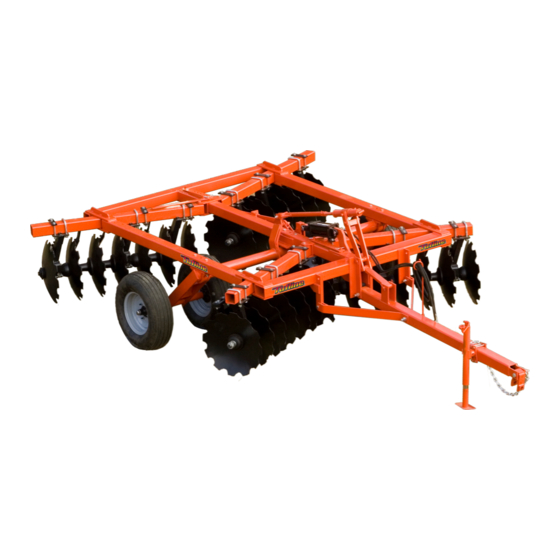
- Page 1 O P E R A T O R ' S M A N U A L DISK HARROWS TW6 SERIES TW6_16259_10/2018...
-
Page 2: Introduction Ii
Use only genuine Tufline service parts. Substitute parts will void the warranty and may not meet stan- dards required for safe and satisfactory operation. Record the model number and serial number of your... -
Page 3: Table Of Contents
TABLE OF CONTENTS INTRODUCTION ..........ii SPECIFICATIONS / GENERAL INFORMATION . -
Page 4: Specifications / General Information
SPECIFICATIONS Model # Blades # # of Spacing Appox. Weight Bearings Width TW6102022 20-22" 10 1/2" 60-75 3231# TW6102024 20-24" 10 1/2" 60-75 3511# TW692422 24-22" 9" 9' 6" 65-75 3349# TW692424 24-24" 9" 9' 6" 65-75 3679# TW692822 28-22" 9"... - Page 5 SPECIFICATIONS, Con't. Model # Blades # # of Spacing Appox. Weight Bearings Width TW962822SF 28-22" 9" 10' 6" 65-75 4533# TW692824SF 28-24" 9" 10' 6" 65-75 4869# TW6102422SF 24-22" 10 1/2" 10' 6" 70-85 4595# TW6102424SF 24-24" 10 1/2" 10' 6" 70-85 4883# TW693222SF...
- Page 6 SAFETY & INSTRUCTIONAL DECALS ATTENTION! BECOME ALERT! YOUR SAFETY IS INVOLVED! FAILURE TO FOLLOW THESE INSTRUCTIONS COULD RESULT IN SERIOUS INJURY OR DEATH Replace Decals Immediately If Damaged!
-
Page 7: Safety Decals 4
SAFETY REFLECTOR DECALS ATTENTION! BECOME ALERT! YOUR SAFETY IS INVOLVED! FAILURE TO FOLLOW THESE INSTRUCTIONS COULD RESULT IN SERIOUS INJURY OR DEATH Replace Decals Immediately If Damaged! Check that all reflector decals are installed and in good condition. Replace if decals are worn or damaged. Reflector Decals 9”... -
Page 8: Safety Rules
SAFETY RULES ATTENTION! BECOME ALERT! YOUR SAFETY IS INVOLVED! • OPERATION (cont’d.) MAINTENANCE • Always wear relatively tight and belted cloth- • Do not operate or transport on steep slopes. ing to avoid getting caught in moving parts. • Do not stop, start, or change directions sud- Wear sturdy, rough-soled work shoes and denly on slopes. - Page 9 SAFETY RULES ATTENTION! BECOME ALERT! YOUR SAFETY IS INVOLVED! MAINTENANCE (cont’d.) CONTACT A PHYSICIAN IMMEDIATELY IF FLUID ENTERS SKIN OR EYES. DO NOT • connecting equipment or hoses or performing DE-LAY. any hydraulic maintenance, purge any air in hydraulic system by operating all hydraulic • Keep all persons away from operator con- functions several times.
- Page 10 SAFETY RULES ATTENTION! BECOME ALERT! YOUR SAFETY IS INVOLVED! • OPERATION (cont’d.) MAINTENANCE • Always wear relatively tight and belted cloth- • Do not operate or transport on steep slopes. ing to avoid getting caught in moving parts. • Do not stop, start, or change directions sud- Wear sturdy, rough-soled work shoes and denly on slopes.
- Page 11 SAFETY RULES ATTENTION! BECOME ALERT! YOUR SAFETY IS INVOLVED! MAINTENANCE (cont’d.) CONTACT A PHYSICIAN IMMEDIATELY IF FLUID ENTERS SKIN OR EYES. DO NOT • connecting equipment or hoses or performing DE-LAY. any hydraulic maintenance, purge any air in hydraulic system by operating all hydraulic • Keep all persons away from operator con- functions several times.
-
Page 12: Dealer Instructions
Dealer Instructions Pre-Assembly Photo 3 The TW6 is shipped from the factory partially assembled (Photo 1). Move the unit to a suit- Photo 1 Photo 1 Photo 4 able, open, flat location for complete assembly (Photo 2). When completing this portion of the assembly Photo 2 let. - Page 13 from the wheels. Remove the wheel extensions Photo 8 (Ref. 1, Photo 6) from the wheel carriage by removing the 3/8” x 3” Gr. 5 bolt (Ref. 2, Photo Photo 6 complete, tighten nuts accordingly. Please see Bolt Torque Chart (Page 45) for proper torque information.
- Page 14 the frame from rolling off the pallet and causing the pallet (Photo 13). When all bands have potential serious injury. While the frame is rest- been cut, lower the frame to the tongue lying on Photo 13 Photo 11 ing on the pallet, relocate the sling from its cur- the ground.
- Page 15 7/8” x 6 ½” Gr. 5 bolt to connect the rocker arm Photo 17 & link bar to the frame (Ref. 3, Photo 15). Once tongue has been connected to frame, fold the Photo 15 Photo 18 spring rod assembly (Ref. 1, Photo 16) over to meet the rocker arm &...
- Page 16 & 8 in Parts Catalog. Remove the 5/8” x 6” Gr. Photo 20 2 bolts from the front and rear slide plates (Photo 21) to accommodate the gang beams. Slide the rear beams through the slot in frame (Photo 22) till they meet the rear slide plate in Photo 23 should be rolled off of pallet.
- Page 17 process, be careful handling the large parts. rectly adjust the spacing between the rear gang They are heavy and dropping them could lead assemblies, drop a plumb bob from the rear of to moderate or serious injury. Photo 27 Photo 25 the main frame directly under the center of the center beam.
- Page 18 Photo 28 the cardboard box in Photo 18. Mount the SMV sign to the mounting bracket using 1/8” x ½” Gr. 2 round head machine screws. Now mount the mounting bracket to the rear of frame using 5/16” x 1” Gr. 2 carriage bolts (Photo 29). When mounted, tighten nuts accordingly.
- Page 19 Safety Light Assembly TW6 The light mount brackets (Ref.1) are attached to Chart (Page 45) for proper torque information. the rear gang beams from the factory. It may be Turn the light unit so that the red and orange neccesary to loosen the 5/8” nylon hex nut(Ref.4) lights are to the rear and the orange is on the in order to rotate the light mount bracket and outside.
- Page 20 Safety Light Assembly TW6 (cont'd) Figure 1 TW6 Safety Light Assembly Figure 2 Set of Lower Hitch Bushings for iMatch (Sold Separately) Begin assembling the wire harness from the long end of the Y harness (Ref. 4) into the fur- front of the unit.
- Page 21 hydraulic maintenance, purge any air in (Dealer’s Responsibility) hydraulic system by operating all hydraulic Inspect the equipment thoroughly after assembly functions serval times. Do this before putting to be certain it is set up properly before deliver- into service or allowing more to approach the ing it to the customer.
-
Page 22: Operation 19
Operation • NEVER GO UNDERNEATH EQUIPMENT. Safety is a primary concern in the design and Never place any part of the body underneath manufacture of our products. Unfortunately, our equipment or between moveable parts even efforts to provide safe equipment can be wiped when the engine has been turned off. - Page 23 GETTING STARTED 5 simple adjustments to remember to help (Figure B), and a less aggressive gang angle operate disk properly. (Figure C). It is recommended the unit be set with the general purpose gang angles first. STEP 1: SET INITIAL GANG ANGLE There are additional gang angle settings for the Setting the initial gang angle on the DH16 disk front and rear other than the three basic set-...
- Page 24 Figure C 16º Rear 18º Front To adjust the front or rear gang angles remove proper hole in gang adjusting bar. This will pro- the angle adjusting lever (Ref. 2, Photo 1A) vide leverage to shift the slide plate (Ref. 5, Photo 1B) whichever direction you desire for from the hose holder (Ref.
- Page 25 Most operating problems are caused by unequal Disengage the tractor and engage the parking pressure and penetration of the front and rear brake before dismounting the tractor. Replace gangs. Adjust the leveling system to obtain equal the pin (Ref. 5, Photo 3) in the depth control bar penetration by the front and rear gangs and sta- through the nearest hole (Ref.
-
Page 26: Trouble Shooting 23
Gang Addjustment Troubleshooting 1. Unit not tracking or is fishtailing A. Adjust leveling system to increase weight on the rear of the disk and make sure the wheels have some weight on them B. Disk assembled incorrectly. Refer to assem- bly instructions. -
Page 27: Owner Service 24
Owner Service 24... - Page 28 Lubrication(cont’d.) When gang component replacement is required, on the mainframe where the gang angle turn- carefully observe all safety issues. Place unit buckles slide. on level ground prior to gang drop. Also make Lubricate the following at the end of each use sure that gangs are blocked to keep them from period : rolling in either direction.
-
Page 29: Assembly Schematic 26
TW6 Assembly Schematic Figure 3 DUAL WHEELS ARE STANDARD ON ALL MODELS Assembly Schematic 26... -
Page 30: Parts Catalog 27
TW6 Main Parts Schematic Figure 4 27 27 TW6 Main Parts List Ref.# Part # Description Qty. 11434 MAIN FRAME- TW6928,TW6932 11436 MAIN FRAME- TW6936 TW6940 12413 GANG ANGLE ADJUSTMENT BAR, REAR- TW6928, TW6932 12416 GANG ANGLE ADJUSTMENT BAR, REAR-TW6936, TW6940 9979 HAIR PIN CLIP... - Page 31 TW6 Main Parts List (cont’d) Ref.# Part # Description Qty. T-24 LOCKWASHER, 5/8" T-22 HEX NUT, 5/8" 9661 HEX BOLT, 5/8" X 6 1/2" GR. 2 9651 HEX BOLT, 5/8" X 3" GR. 2 12511 1/8" X 1 3/4" STRAIGHT GREASE FITTING T-58 WHEEL CARRIAGE BEARING TOP T-57...
- Page 32 TW6 Drawbar Parts Schematic Figure 5 TW6 Wheel Parts Schematic Figure 6 DUAL WHEELS ARE STANDARD ON ALL MODELS Parts Catalog 29...
- Page 33 TW6 Drawbar Parts List Ref.# Part # Description Qty. 9027 TONGUE, DH16 T-2665 TONGUE CLEVIS T-933 TONGUE JACK 15189 ASSEMBLY MANUAL TUBE AND CAP T-465 HOSE HOLDER T-772 HEX BOLT, 7/8" X 5" GR. 5 T-19 HEX NUT, 7/8" T-21 LOCK WASHER, 7/8"...
- Page 34 Optional ShockFlex Hangers TW6 Front Gang Parts Schematic Figure 7 TW6 Front Gang Parts List Ref.# Part # Description Qty. 11971 3/4" U-BOLT FOR 4 X 4 BEAM 12449 4" X 4" X 56" GANG BEAM TW6928 FRONT 12452 4" X 4" X 65" GANG BEAM TW6932 FRONT 12454 4"...
- Page 35 TW6 Front Gang Parts List (cont’d) Ref.# Part # Description Qty. TMDR RELUBE TRUNNION BEARING HOUSING T-604 SEALED BEARING, 1 1/2" T-604R RELUBE BEARING, 1 1/2" T-729 SNAP RING, 4" T-103 SPACER SPOOL, 1 1/2" X 9" T-492 END WASHER, 1 1/2" T-728 LOCKWASHER, 1 1/2"...
- Page 36 Optional ShockFlex Hangers TW6 Rear Gang Parts Schematic Figure 8 TW6 Rear Gang Parts List Ref.# Part # Description Qty. 11971 3/4" U-BOLT FOR 4X4 BEAM 12450 4" X 4" X 66" GANG BEAM- TW6928 REAR 12453 4" X 4" X 75" GANG BEAM- TW6932 REAR 12455 4"...
- Page 37 TW6 Rear Gang Parts List (cont’d) Ref.# Part # Description Qty. TMDR RELUBE TRUNNION BEARING HOUSING T-604 SEALED BEARING, 1 1/2" T-604R RELUBE BEARING, 1 1/2" T-729 SNAP RING, 4" T-103 SPACER SPOOL, 1 1/2" X 9" T-492 END WASHER, 1 1/2" T-728 LOCKWASHER, 1 1/2"...
- Page 38 15707 MODEL TW6928 DECAL 15708 MODEL TW6932 DECAL 15709 MODEL TW6936 DECAL 15710 MODEL TW6940 DECAL 15658 3 1/2" TUFLINE LOGO DECAL 15715 DH16 OPERATORS MANUAL 15199 9" RED REFLECTOR 15200 9" YELLOW REFLECTOR 15361 9" FLUORESCENT ORANGE DECAL 15718...
-
Page 39: Optional Equipment 36
Optional Equipment Heavy Scraper Kit Figure 10 TW6 Series DH16 Series Heavy Scraper Kit Model Numbers SK9286 for the TW6928 SK9326 for theTW6932 SK9366 for the TW6936 SK9406 for the TW6940 Optional Equipment 36... - Page 40 Heavy Scraper Kit Parts List Ref.# Part # Description Qty. 12891 SCRAPER MOUNT BRACKET 12894 SCRAPER BAR TOP PLATE T-747 HEX BOLT, 5/8" X 6" GR. 2 T-22 HEX NUT, 5/8" T-24 LOCKWASHER, 5/8" 11082 HEX BOLT, 1/2" X 2 1/2" GR. 2 9226 FLANGE LOCK NUT, 1/2"...
- Page 41 Heavy Scraper Kit Mount Instructions & blade assemblies(Ref. #16) to thr bottom of the scrapper bar (Ref. #13), use 2-hole clam[ * NOTE- When attaching heavy scraper kit, do NOT (Ref,#12) on top of the scraper bar (Ref. #13) tighten any hardware until stated in directions. and fasten together with 1/2"...
- Page 42 Optional Equipment Cont’d Center Sweep Kit Figure 11 Part Number 11476 Ref.# Part # Description Qty. 10388 SHANK BRACKET 4” BEAM 9175 SHANK HOLDER 4” BEAM 10602 BALK BREAKER SHANK 9192 HEX BOLT, 5/8” X 2 1/2”, GR. 5 T-22 HEX NUT, 5/8”...
- Page 43 T-27 HEX NUT, 3/4” *Note: Item #3, Part# T-OR15 is not included with this assembly. The T-OR15 is standard equipment on the rear gangs of the TW6 series. Outrigger Kit Mounting Instructions Reference Figure 12 the 3/4” x 3 1/2” Gr. 5 bolt (Ref. #6) is pulled out as far as possible before tightening.
- Page 44 TW6 Roller Basket Schematic TW6 Roller Basket Kit Model Numbers TW6 Roller Basket Parts List Ref.# Part # Description Qty. 16071 MOUNT WELDMENT 16076 ARM WELDMENT 16080 SPRING ROD WELDMENT T-510 SPRING HOUSING T-509 ADJUSTING SPRING 8 1/2" 16082 PIVOT PLATE 16086 TOOL BAR 141", TW6928 16087...
- Page 45 TW6 Roller Basket Parts List (cont'd) Ref.# Part # Description Qty. 16 T-698 FLAT WASHER, 1 1/8" 17 10332 LOCK NUT, 1" 18 T-26 HEX NUT, 1/2" 19 T-22 HEX NUT, 5/8 20 T-18 HEX NUT, 1 1/8" 21 16079 ARM TOOLBAR MOUNT PLATE 22 11138 2"...
- Page 46 Roller Basket Assembly Assembly mount properly. Next attach the arm and spring rod assembly using the two mount pins (Photo 32). WARNING After both sides have been mounted start assem- bling the roller baskets together. Outer hangers are pre assembled onto the outer end of the roller bas- Mounting bracket, straps, arm, spring rod ket (Photo 33).
- Page 47 Roller Basket Assembly (cont'd.) Adjusting Roller Basket Loosen jam nuts (Photo38, Ref. 1) and hex Photo 35 nuts (Photo38, Ref. 2) on both ends of each spring rod assembly. Adjust the rear facing hex nut on spring rod assemblies to desired height. Photo 38 assembly (Photo35).
-
Page 48: Bolt And Torque Chart 45
TW6 Series gang bolt torquee 400 lbs-ft, then tighten nut clockwise 180* Bolt and Torque Chart 45... -
Page 49: Notes 46
Notes Notes 46... - Page 50 PART NO. 16259 © 2017 Monroe Tufline Manufacturing, Inc. All Rights Reserved...
Need help?
Do you have a question about the TW6 Series and is the answer not in the manual?
Questions and answers