
Subscribe to Our Youtube Channel
Related Manuals for Tufline TW6 Series


Summary of Contents for Tufline TW6 Series
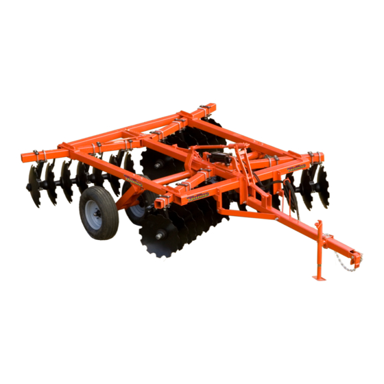
- Page 1 O P E R A T O R ' S M A N U A L TW6 SERIES DISC www.monroetufline.com 14321 2/19/2009...
-
Page 2: Introduction Ii
Use only genuine Tufline service parts. Substitute parts will void the warranty and may not meet stan- dards required for safe and satisfactory operation. Record the model number and serial number of your... -
Page 3: Table Of Contents
GENERAL INFORMATION The purpose of this manual is to assist you your particular situation. in operating and maintaining your TUFLINE The illustrations and data used in this DISC. Read it carefully. It furnishes infor- manual were current at the time of print- mation and instructions that will help you ing. -
Page 4: Specifications
SPECIFICATIONS Model # Blades # of Spacing Appox. Weight Bearings Width TW6102022 20-22” 10 1/2” 9’ 60-75 3101# TW6102024 20-24” 10 1/2” 9’ 60-75 3381# TW692422 24-22” 9” 9’ 6” 65-75 3219# TW692424 24-24” 9” 9’ 6” 65-75 3549# TW692822/3 28-22”... -
Page 5: Safety Decals 2
SAFETY & INSTRUCTIONAL DECALS ATTENTION! BECOME ALERT! YOUR SAFETY IS INVOLVED! FAILURE TO FOLLOW THESE INSTRUCTIONS COULD RESULT IN SERIOUS INJURY OR DEATH Check that all safety decals are Replace Decals Immediately If Damaged! installed and in good condition. Replace if decals are worn or damaged. -
Page 6: Safety Rules
SATETY RULES ATTENTION! BECOME ALERT! YOUR SAFETY IS INVOLVED! Safety is a primary concern in the design and death. manufacture of our products. Unfortunately, our efforts to provide safe equipment can be wiped • Keep hands and body away from pressurized out by an operator’s single careless act. - Page 7 SATETY RULES ATTENTION! BECOME ALERT! YOUR SAFETY IS INVOLVED! PREPARATION (cont’d) sharply, kinked, frayed, pinched, or come into • Use extreme care and reduce ground speed contact with any moving parts. Operate move- on slopes and rough terrain. able components through full operational range to check clearances.
- Page 8 SATETY RULES ATTENTION! BECOME ALERT! YOUR SAFETY IS INVOLVED! OPERATION (cont’d) • Air in hydraulic systems can cause erratic • Keep hands, feet, hair, and clothing away from operation and allows loads or equipment compo- equipment while engine is running. Stay clear of nents to drop unexpectedly.
- Page 9 SATETY RULES ATTENTION! BECOME ALERT! YOUR SAFETY IS INVOLVED! MAINTENANCE (cont’d) damage. Hoses must not be twisted, bent sharp- moveable parts even when the engine has been ly, kinked, frayed, pinched, or come into contact turned off. Hydraulic system leak down, hydrau- with any moving parts.
-
Page 10: Parts Catalog
FIG. 1 7 Parts Catalog... - Page 11 Parts Catalog 8...
- Page 12 9 Parts Catalog...
- Page 13 Parts Catalog 10...
- Page 14 11 Parts Catalog...
- Page 15 Parts Catalog 12...
-
Page 16: Assembly
MAIN FRAME ASSEMBLY 1. Assemble wheel hub on spindle according to Fig. 4 and instructions on page 15. 2. Insert the spindles into wheel carriage tubes and insert the 3/8” x 3” Gr. 5 hex bolt, Fig 1, Ref. 24. 3. - Page 17 GANG POSITIONING 1. Mount the tubular gang hangers, Ref. 1, Fig. 2, to the gangs at the bearing housing using the ½ “ x 3 ½ “ Gr. 5 hex bolts, Ref. 2. Be sure the “lean” of the hanger is with the concavity of the blade.
-
Page 18: Maintenance
FIG. 4 SPINDLE & HUB ASSEMBLY 1. Refer to Fig. 4. Using the utmost cleanliness, pack the wheel bearings with grease and stuff the hub. 2. Install the large bearing, Ref. 4, and seal, Ref. 3, with the seal lip toward the hub. 3. - Page 19 FIG. 6 LEVELING SYSTEM The leveling system automatically controls the harrow from full depth penetration all the way up to transport height. Once it is set for a particular tractor drawbar height, only minor adjustments will ever be required. The springs allow pressure controlled flexibility when obstructions and/or uneven terrain are encountered.
- Page 20 MAINTENANCE AND LUBRICATION LUBRICATION Lubricate the following every 50 hours of operation: Wheel carriage bearings. Leveling tube. Leveling rocker pivot. Lubricate the following every 150 hours of operation: Optional regreasible bearings. Lubricate at the end of each season: Transport wheel bearings. Pack with heavy wheel bearing grease. MAINTENANCE Check all gang axle nuts for proper torque every 150 hours.
-
Page 21: Optional Equipment 18
Optional Equipment 18... - Page 22 19 Optional Equipment...
- Page 23 Optional Equipment 20...
-
Page 24: Disc Adjustment
ADJUSTMENTS PRIOR TO FIELD TEST These adjustments can be made when the harrow is completely assembled and attached to the tractor. 1. Adjust until the rear blades touch the ground when the front blades are about 2” above the ground. 2. -
Page 25: Bolt Size And Bolt Torque Chart 22
SAE TORQUE CHART NOTE: Chart shows bolt thread sizes and corresponding head (wrench) sizes for stan- dard SAE bolts. THIS IS STANDARD FOR SAE GUIDE FOR ALL MONROE TUFLINE IMPLEMENTS MARKING ON HEAD Diameter Wrench SAE 2 SAE 5 SAE 8... -
Page 26: Trouble Shooting
TROUBLE SHOOTING CHART PROBLEM POSSIBLE SOLUTION Furrow gradually worsening in low Tilt disc down in rear if necessary, far enough to area toward the center of each pass see if it will start to bed in center slightly. If this can sometimes accompanied by slightly be done, the leveling adjustment will correct the high area at the edge of the cut. - Page 27 Bending or breaking outside Do not make sharp turns with discs in the ground. front disc blades or gang axle. Keep gang axle nuts tightened to torque chart specifica- tions. Bearing problems or wear on Gang axles may be bent thus causing gangs to wobble. bearing housings.
-
Page 28: Warranty
Monroe-Tufline’s obligation under this Warranty is limited to, at Monroe-Tufline’s option, the repair or replacement, free of charge, of the product if Monroe-Tufline, in its sole discretion, deems it to be defective or in noncompliance with this Warranty. Such parts shall be provided by the selling dealer to the user during regular working hours. If... - Page 29 Monroe-Tufline’s obligation under this Warranty is limited to, at Monroe-Tufline’s option, the repair or replace- ment, free of charge, of the product if Monroe-Tufline, in its sole discretion, deems it to be defective or in noncompliance with this Warranty. The selling dealer shall provide such parts to the user during regular work- ing hours.
-
Page 30: Notes
NOTES: _________________________________ ________________________________________ ________________________________________ ________________________________________ ________________________________________ ________________________________________ ________________________________________ ________________________________________ ________________________________________ ________________________________________ ________________________________________ ________________________________________ ________________________________________ ________________________________________ ________________________________________ ________________________________________ ________________________________________ ________________________________________ ________________________________________ ________________________________________ ________________________________________ ________________________________________ 27 Notes... -
Page 31: Warranty Registration 28
________________________________________ ________________________________________ ________________________________________ ________________________________________ ________________________________________ ________________________________________ ________________________________________ FILL OUT REGISTRATION CARD BELOW AND MAIL TO: MONROE TUFLINE Attn; Owner Registration PO BOX 7755 Columbus, MS 39705 ------------------------------------------------------------------- OWNER WARRANTY REGISTRATION NAME___________________________ ADDRESS / CITY / STATE__________________________ _________________________ DEALER NAME ______________________________ CITY / STATE_________________________... - Page 32 PART NO. 14321 MONROE TUFLINE MFG. CO., INC. PO BOX 7755 / 2219 TUFLINE LANE COLUMBUS, MS 39705-0004 (662)328-8347 www.monroetufline.com © 2008 Monroe Tufline Manufacturing, Inc. All Rights Reserved...
Need help?
Do you have a question about the TW6 Series and is the answer not in the manual?
Questions and answers