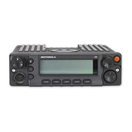
Motorola ASTRO XTL 5000 Basic Service Manual
Digital mobile radio hf/uhf range 1/uhf range 2/ 700–800 mhz
Hide thumbs
Also See for ASTRO XTL 5000:
- Detailed service manual (528 pages) ,
- Basic service manual (170 pages) ,
- User manual (162 pages)
Table of Contents
Advertisement
Advertisement
Table of Contents
Troubleshooting


Need help?
Do you have a question about the ASTRO XTL 5000 and is the answer not in the manual?
Questions and answers