Motorola ASTRO XTS 3000 Service Manual
Hide thumbs
Also See for ASTRO XTS 3000:
- Service manual (236 pages) ,
- User manual (104 pages) ,
- Basic service manual (48 pages)
Table of Contents
Advertisement
Advertisement
Table of Contents

Related Manuals for Motorola ASTRO XTS 3000


Summary of Contents for Motorola ASTRO XTS 3000
- Page 1 ® ™ ASTRO 3000 Digital Portable Radios Basic Service Manual...
- Page 3 XTS 3000 ASTRO Digital Radio Basic Service Manual © March 2004 Motorola, Inc. 68P81083C85-A All Rights Reserved March 2004...
- Page 4 Trademarks MOTOROLA and the Stylized M logo are registered in the US Patent & Trademark Office. All other product or service names are the property of their respective owners.
-
Page 5: Table Of Contents
Table Contents Contents ■ ■ ■ ■ ■ ■ ■ ■ ■ ■ ■ ■ ■ ■ ■ ■ ■ ■ ■ ■ ■ ■ ■ ■ ■ ■ ■ ■ ■ ■ ■ ■ ■ ■ ■ ■ ■ ■... - Page 6 Contents 7.2.1 Preventative Maintenance ....... . 7.2.2 Reference Oscillator Alignment......7.2.2.1 Initial Setup Using R-2670 and 8900 Series Analyzers .
-
Page 7: Safety Information
This radio is restricted to occupational use only to satisfy FCC RF energy exposure requirements. Before using this product, read the RF energy awareness information and operating instructions in the Product Safety and RF Exposure booklet enclosed with your radio (Motorola part number 6881095C98) to ensure compliance with RF energy exposure limits. - Page 8 Chapter 1: Safety Information This page intentionally left blank. 68P81083C85-A March 2004...
-
Page 9: Chapter 2: Model Charts And Test Specifications
Chapter Model Charts and Test Specifications ■ ■ ■ ■ ■ ■ ■ ■ ■ ■ ■ ■ ■ ■ ■ ■ ■ ■ ■ ■ ■ ■ ■ ■ ■ ■ ■ ■ ■ ■ ■ ■ ■ ■ ■... -
Page 10: Specifications For Vhf Radios
Specifications for VHF Radios Chapter 2: Model Charts and Test Specifications 2.1 Specifications for VHF Radios ■ ■ ■ ■ ■ ■ ■ ■ ■ ■ ■ ■ ■ ■ ■ ■ ■ ■ ■ ■ ■ ■ ■ ■ ■... - Page 11 XTS 3000 ASTRO Digital Radio Basic Service Manual Specifications for VHF Radios Table 2-1 General Specifications (Continued) General Specifications 6.58” x 2.44” x 1.83”/6.58” x 2.34” x.97” (167.13mm x 61.90mm x 46.42mm/167.13mm x 59.49 mm x 24.56 mm) Weight: (w/Antenna): Less Battery: 14.10 oz (383 gm) With Ultra-High Cap.
-
Page 12: Specifications For Uhf Radios
Specifications for UHF Radios Chapter 2: Model Charts and Test Specifications Table 2-3 Transmitter Specifications (Continued) Transmitter FM Hum and Noise (typical) (Companion Receiver): 25/30 kHz —48dB 12.5 kHz —42dB Distortion: 2% Typical Modulation Limiting: 25/20 kHz chnls +5.0kHz 20 kHz chnls +4.0 kHz 12.5kHz chnls +2.5kHz Emissions Designators: 20K0F1E, 16K0F3E, 11K0F3E, 8K0F1D and 8K10F1E... - Page 13 XTS 3000 ASTRO Digital Radio Basic Service Manual Specifications for UHF Radios Table 2-4 General Specifications (Continued) General Specifications Ultra-High-Capacity NiCd : NTN8294A or Ultra-High-Capacity NiCd FM: NTN8295* or Ultra-High-Capacity NiMH FM IS: NTN8299A* Optional FM (Factory Mutual) Battery: • FM Intrinsically Safe: Class I, II, III, Division 1, Groups D, F, and G Dimensions (HxWxD): 2.44”...
- Page 14 Specifications for UHF Radios Chapter 2: Model Charts and Test Specifications Table 2-4 General Specifications (Continued) General Specifications With NiMH FM IS: 23.45 oz (644 gm) * Specifications subject to change without notice. Table 2-5 Receiver Specifications Receiver Frequency Range: 403–520 MHz Bandwidth: 70 MHz...
-
Page 15: Specifications For 800 Mhz Radios
XTS 3000 ASTRO Digital Radio Basic Service Manual Specifications for 800 MHz Radios Table 2-6 Transmitter Specifications (Continued) Transmitter Modulation Limiting: 25/30 kHz chnls +5.0 kHz 20kHz chnls +4.0kHz 12.5kHz chnls +2.5kHz Emissions Designators: 20K0F1E, 16K0F3E, 11K0F3E, 15K0F1D and 8K10F1E * Specifications subject to change without notice. - Page 16 Specifications for 800 MHz Radios Chapter 2: Model Charts and Test Specifications Table 2-7 General Specifications (Continued) General Specifications Optional FM (Factory Mutual) Battery: • FM Intrinsically Safe: Class I, II, III, Division 1, Groups D, F, and G Dimensions (HxWxD): 2.44”...
- Page 17 XTS 3000 ASTRO Digital Radio Basic Service Manual Specifications for 800 MHz Radios Table 2-8 Receiver Specifications (Continued) Receiver Selectivity (25kHz Adjacent Channel): —70dB Spurious Rejection: —70dB Frequency Stability (-30 to +60°C; 25°C reference): + .00015% Rated Audio: 500mW Distortion (At Rated Audio): 3% Typical Channel Spacing: 25 kHz...
- Page 18 Specifications for 800 MHz Radios Chapter 2: Model Charts and Test Specifications This page intentionally left blank. 2-10 68P81083C85-A March 2004...
-
Page 19: Chapter 3: Overview
Chapter Overview ■ ■ ■ ■ ■ ■ ■ ■ ■ ■ ■ ■ ■ ■ ■ ■ ■ ■ ■ ■ ■ ■ ■ ■ ■ ■ ■ ■ ■ ■ ■ ■ ■ ■ ■ ■ ■ ■ ■... -
Page 20: Radio Description
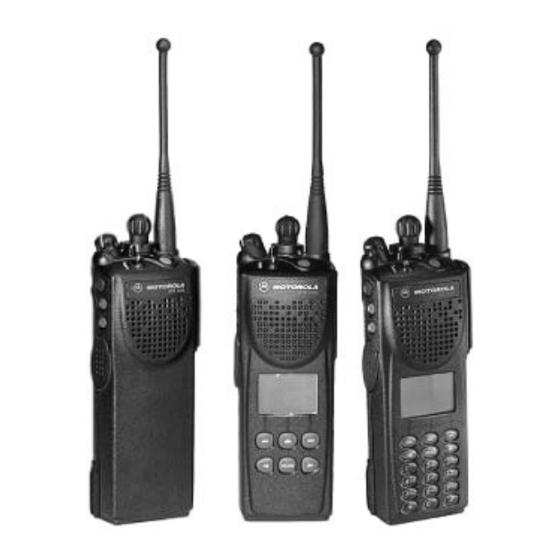
800MHz band; radios in the UHF and VHF bands will be available by the end of 1996. One of the newest in a long line of quality Motorola products, the ASTRO Digital XTS 3000 radio provides improved voice quality across more coverage area. The digital process called “embedded signalling”... -
Page 21: Flashport
■ ■ The ASTRO Digital XTS 3000 radio utilizes Motorola’s revolutionary FLASHPort technology. FLASHPort makes it possible to add software that drives the radio’s capabilities both at the time of purchase and later on. Previously, changing a radio’s features and capabilities meant significant modifications, or buying a new radio. - Page 22 FLASHPort Chapter 3: Overview This page intentionally left blank. 68P81083C85-A March 2004...
-
Page 23: Chapter 4: Basic Maintenance
Chapter Basic Maintenance ■ ■ ■ ■ ■ ■ ■ ■ ■ ■ ■ ■ ■ ■ ■ ■ ■ ■ ■ ■ ■ ■ ■ ■ ■ ■ ■ ■ ■ ■ ■ ■ ■ ■ ■ ■ ■ ■... -
Page 24: Cleaning External Plastic Surfaces
Cleaning External Plastic Surfaces Chapter 4: Basic Maintenance 4.1.2.1 Cleaning External Plastic Surfaces The detergent-water solution should be applied sparingly with a stiff, nonmetallic, short-bristled brush to work all loose dirt away from the radio. A soft, absorbent, lint-free cloth or tissue should be used to remove the solution and dry the radio. - Page 25 Elastomer technology materials used for seals in rugged portable radios can age with time and environmental exposure. Therefore, Motorola recommends that rugged radios be checked annually to assure the watertight integrity of the radio.
- Page 26 XTS 3000 R Radios Only Chapter 4: Basic Maintenance This page intentionally left blank. 68P81083C85-A March 2004...
-
Page 27: Chapter 5: Recommended Test Equipment And Service Aids
The “Characteristics” column is included so that equivalent equipment may be substituted; however, when no information is provided in this column, the specific Motorola model listed is either a unique item or no substitution is recommended. -
Page 28: Service Aids
“Replacement Parts Ordering” section located on the inside back cover of this manual. While all of these items are available from Motorola, most are standard shop equipment items, and any equivalent item capable of the same performance may be substituted for the item listed. -
Page 29: Field Programming Equipment
XTS 3000 ASTRO Digital Radio Basic Service Manual Field Programming Equipment Table 5-2 Service Aids (Continued) Motorola Part Description Application Number 01-80357A57 Wall-Mounted Power Used to supply power to the RIB (120 Supply Vac). 01-80358A56 Wall-Mounted Power Used to supply power to the RIB (220 Supply Vac). - Page 30 Field Programming Equipment Chapter 5: Recommended Test Equipment and Service Aids This page intentionally left blank. 68P81083C85-A March 2004...
-
Page 31: Chapter 6: Performance Checks
Chapter Performance Checks ■ ■ ■ ■ ■ ■ ■ ■ ■ ■ ■ ■ ■ ■ ■ ■ ■ ■ ■ ■ ■ ■ ■ ■ ■ ■ ■ ■ ■ ■ ■ ■ ■ ■ ■ ■ ■ ■... -
Page 32: Test Mode
Test Mode Chapter 6: Performance Checks 6.2 Test Mode ■ ■ ■ ■ ■ ■ ■ ■ ■ ■ ■ ■ ■ ■ ■ ■ ■ ■ ■ ■ ■ ■ ■ ■ ■ ■ ■ ■ ■ ■ ■ ■... -
Page 33: Rf Test Mode
XTS 3000 ASTRO Digital Radio Basic Service Manual RF Test Mode Table 6-2 Front Panel Access Test Mode Displays (Continued) Name of Display Description Appears Encryption Type 1 Type of encryption being used. When the radio is secure equipped. Encryption Type 2 Type of encryption being used. -
Page 34: Display Description
RF Test Mode Chapter 6: Performance Checks Transmit into a load when keying a radio under test. Table 6-3 Test Frequencies Test Channel UHF Band 1 UHF Band 2 800MHz TX#1 136.025 403.100 450.025 806.0125 RX#1 136.075 403.150 450.075 851.0625 TX#2 142.125 424.850... -
Page 35: Control Top And Keypad Test Mode
XTS 3000 ASTRO Digital Radio Basic Service Manual Control Top and Keypad Test Mode 6.2.3 Control Top and Keypad Test Mode See procedure below to enter control top and keypad test mode. Procedure 6-3 Entering Control Top and Keypad Test Mode Next, press and hold the Top Programmable Button;... - Page 36 Control Top and Keypad Test Mode Chapter 6: Performance Checks The following table contains information for receiver performance checks. Table 6-5 Receiver Performance Checks Test Name System Analyzer Radio Test Set Comments PTT to Frequency error Reference Mode: PWR MON TEST Frequency 4th channel test...
- Page 37 XTS 3000 ASTRO Digital Radio Basic Service Manual Control Top and Keypad Test Mode The following table contains information necessary for transmitter performance checks. Table 6-6 Transmitter Performance Checks System Test Name Radio Test Set Comments Analyzer Reference Mode: PWR MON TEST MODE, 4 PTT to Frequency error...
- Page 38 Control Top and Keypad Test Mode Chapter 6: Performance Checks Table 6-6 Transmitter Performance Checks (Continued) System Test Name Radio Test Set Comments Analyzer Talkaround Change frequency Conventional As above Deviation: Modulation to conventional talkaround 800MHz: >3.8Hz but < (radios with talkaround personality conventional,...
-
Page 39: Chapter 7: Alignment Procedure
■ ■ The following procedures are to be used for the alignment of all Motorola ASTRO Digital portable radios with HP8901B Modulation Analyzer and R2670 Communication Analyzer. These procedures are to be used in conjunction with the instructions listed in the Motorola Radio Service Software (RSS) / Customer Programming Software (CPS) tuner under the Help key for each test to be performed. - Page 40 General Chapter 7: ALIGNMENT PROCEDURE Figure 7-1 Radio Alignment Test Setup SYSTEM ANALYZER 30 dB PAD OR COUNTER TRANSMIT 30 dB PAD WATTMETER RF GENERATOR SMA-BNC RECEIVE 58-80348B33 SET TO APPROX. 450mV FOR Tx AUDIO IN BATTERY AUDIO GENERATOR RADIO TEST SET ELIMINATOR RTX-4005B...
- Page 41 XTS 3000 ASTRO Digital Radio Basic Service Manual General Figure 7-2 RSS Service Menu Layout SERVICE F2 - TRANSMITTER ALIGNMENT MENU F1 - HELP F2 - REFERENCE OSCILLATOR ALIGNMENT F3 - TRANSMIT POWER ALIGNMENT F4 - TRANSMIT DEVIATION BALANCE (COMPENSATION) ALIGNMENT F5 - TRANSMIT DEVIATION LIMIT ALIGNMENT F10 -...
-
Page 42: Reference Oscillator
Reference Oscillator Chapter 7: ALIGNMENT PROCEDURE Some of the following screens may vary depending upon the radio under test and the version of radio service software you are using. Refer to your Radio Service Software user guide. 7.2 Reference Oscillator ■... -
Page 43: Initial Setup Using R-2670 And 8900 Series Analyzers
XTS 3000 ASTRO Digital Radio Basic Service Manual Initial Setup Using R-2670 and 8900 Series Analyzers 7.2.2.1 Initial Setup Using R-2670 and 8900 Series Analyzers Use the following procedure for initial setup using an R–2670 Communication Analyzer. Procedure 7-1 Initial Setup Using the R-2670 Communication Analyzer Set RF Control: to MONITOR. - Page 44 RSS and CPS Procedures Chapter 7: ALIGNMENT PROCEDURE Procedure 7-3 RSS Procedure (Continued) Use the Up/Down arrow key on your PC key board to adjust the reference oscillator softpot value. Allow about 5 seconds for the analyzer’s frequency reading to settle after each change. Adjust the frequency error in accordance with Table 7-1.
-
Page 45: Transmit Power Alignment
XTS 3000 ASTRO Digital Radio Basic Service Manual Transmit Power Alignment 7.3 Transmit Power Alignment ■ ■ ■ ■ ■ ■ ■ ■ ■ ■ ■ ■ ■ ■ ■ ■ ■ ■ ■ ■ ■ ■ ■ ■ ■ ■... -
Page 46: Transmit Deviation Balance (Compensation) Alignment
Transmit Deviation Balance (Compensation) Alignment Chapter 7: ALIGNMENT PROCEDURE Use the following CPS procedure when applicable. Procedure 7-6 CPS Procedure Under the Transmitter Alignments menu, select TX Power High. The screen will indicate the transmit frequencies to be used. Select a frequency field (starting with the highest frequency shown) and select the PTT button to key the radio. -
Page 47: Rss And Cps Procedures
XTS 3000 ASTRO Digital Radio Basic Service Manual RSS and CPS Procedures Use the following procedure for initial setup using an 8900 Series Modulation Analyzer. Procedure 7-8 Initial Setup Using the 8900 Series Modulation Analyzer Press the FM Measurement button. (Error 03-input level too low. This indication is normal until an input signal is applied). -
Page 48: Transmit Deviation Limit Alignment
Transmit Deviation Limit Alignment Chapter 7: ALIGNMENT PROCEDURE Use the following CPS procedure when applicable. Procedure 7-10 CPS Procedure Under the TRANSMITTER ALIGNMENTS menu, double click on TX Deviation Balance (Compensation) to select it. The screen will indicate the transmit frequencies to be used. Select the desired frequency field (starting with the lowest frequency shown on the top of the screen). -
Page 49: Rss And Cps Procedures
XTS 3000 ASTRO Digital Radio Basic Service Manual RSS and CPS Procedures Use the following procedure for initial setup using an R-2670 Communication Analyzer. Procedure 7-11 Initial Setup Using the R-2670 Communication Analyzer Connect a BNC cable between the DEMOD OUT port and the VERT/SINAD DIST/DMM COUNTER IN port of the R-2670. - Page 50 RSS and CPS Procedures Chapter 7: ALIGNMENT PROCEDURE Procedure 7-13 Procedure Using RSS (Continued) Repeat steps 2-6 for the remaining frequencies. Note – test frequency #7 (ex 519.9750 MHz for UHF Range 2) is not normally used and therefore does not require alignment.
-
Page 51: Front End Filter Alignment (Vhf And Uhf Only)
XTS 3000 ASTRO Digital Radio Basic Service Manual Front End Filter Alignment (VHF and UHF only) 7.6 Front End Filter Alignment (VHF and UHF only) ■ ■ ■ ■ ■ ■ ■ ■ ■ ■ ■ ■ ■ ■ ■ ■... -
Page 52: Rss And Cps Procedures
RSS and CPS Procedures Chapter 7: ALIGNMENT PROCEDURE 7.6.1 RSS and CPS Procedures Continue with RSS or CPS procedure below. Use the following RSS procedure when applicable. Procedure 7-16 Procedure Using RSS From the SERVICE menu, press F3 to select the RECEIVER ALIGNMENT menu. - Page 53 XTS 3000 ASTRO Digital Radio Basic Service Manual RSS and CPS Procedures Procedure 7-17 Procedure Using CPS (Continued) Adjust the Up/Down arrow keys under New Softpot Value window to obtain a peak value in the RSSI (Receive Signal Strength Indicator) field. Read RSSI button must be selected to obtain each RSSI reading after adjustment.
-
Page 54: Bit Error Rate Testing
Bit Error Rate Testing Chapter 7: ALIGNMENT PROCEDURE 7.7 Bit Error Rate Testing ■ ■ ■ ■ ■ ■ ■ ■ ■ ■ ■ ■ ■ ■ ■ ■ ■ ■ ■ ■ ■ ■ ■ ■ ■ ■ ■ ■... -
Page 55: Chapter 8: Basic Removal/Installation Procedures
Chapter Basic Removal/Installation Procedures ■ ■ ■ ■ ■ ■ ■ ■ ■ ■ ■ ■ ■ ■ ■ ■ ■ ■ ■ ■ ■ ■ ■ ■ ■ ■ ■ ■ ■ ■ ■ ■ ■ ■ ■ ■ ■... -
Page 56: Battery
Battery Chapter 8: Basic Removal/Installation Procedures 8.2 Battery ■ ■ ■ ■ ■ ■ ■ ■ ■ ■ ■ ■ ■ ■ ■ ■ ■ ■ ■ ■ ■ ■ ■ ■ ■ ■ ■ ■ ■ ■ ■ ■ ■... -
Page 57: Installing The Battery
XTS 3000 ASTRO Digital Radio Basic Service Manual Installing the Battery 8.2.1 Installing the Battery Use the following procedure to install the battery. Procedure 8-1 Battery Installation Turn off the radio and hold it with the back of the radio facing upward. Insert the top edge of the battery into the area at the top of the radio between the radio’s case and chassis. -
Page 58: Belt Clip
Belt Clip Chapter 8: Basic Removal/Installation Procedures 8.3 Belt Clip ■ ■ ■ ■ ■ ■ ■ ■ ■ ■ ■ ■ ■ ■ ■ ■ ■ ■ ■ ■ ■ ■ ■ ■ ■ ■ ■ ■ ■ ■ ■... -
Page 59: Removing The Belt Clip
XTS 3000 ASTRO Digital Radio Basic Service Manual Removing the Belt Clip 8.3.2 Removing the Belt Clip Use the following procedure to remove the belt clip. Procedure 8-4 Belt Clip Removal Hold the battery (with belt clip installed) in one hand so that the top of the battery faces upward, and the front (radio side) of the battery faces you. -
Page 60: Installing The Universal Connector Cover
Installing the Universal Connector Cover Chapter 8: Basic Removal/Installation Procedures 8.4.1 Installing the Universal Connector Cover Use the following procedure to install the universal connector cover. Procedure 8-5 Universal Connector Cover Installation Looking at the antenna side of the radio, insert the top (flat) hooked end of the cover into the slot on the top of the radio, above the universal connector. -
Page 61: Frequency Knob
XTS 3000 ASTRO Digital Radio Basic Service Manual Frequency Knob 8.5 Frequency Knob ■ ■ ■ ■ ■ ■ ■ ■ ■ ■ ■ ■ ■ ■ ■ ■ ■ ■ ■ ■ ■ ■ ■ ■ ■ ■ ■ ■... -
Page 62: Removing The Frequency Knob
Removing the Frequency Knob Chapter 8: Basic Removal/Installation Procedures 8.5.2 Removing the Frequency Knob Use the following procedure to remove the frequency knob. Procedure 8-8 Frequency Knob Removal Hold the radio in one hand so that the top of the radio faces upward, and the front of the radio faces you. -
Page 63: Installing The Volume Knob
XTS 3000 ASTRO Digital Radio Basic Service Manual Installing the Volume Knob 8.6.1 Installing the Volume Knob Use the following procedure to install the volume knob. Procedure 8-9 Volume Knob Installation Place the O-ring (21) inside the volume insert (9), and press it downward until it seats securely at the bottom of the insert. -
Page 64: Partial Exploded View And Parts List
Partial Exploded View and Parts List Chapter 8: Basic Removal/Installation Procedures 8.7 Partial Exploded View and Parts List ■ ■ ■ ■ ■ ■ ■ ■ ■ ■ ■ ■ ■ ■ ■ ■ ■ ■ ■ ■ ■ ■ ■... - Page 65 LABEL, Toggle, Yellow Housing (optional — need if housing is not pad printed) 1505579Z01 COVER, Dust, Universal Connector 3385619B01 LABEL, Motorola, Front (Standard) 3385619B02 LABEL, Motorola, Front (Ruggedized) 3385619B03 LABEL, Motorola, Front (Ruggedized, Yellow) 3505586Z01 Gortex 3205379W01 O-Ring 8-11 68P81083C85-A March 2004...
- Page 66 Partial Exploded View and Parts List Chapter 8: Basic Removal/Installation Procedures This page intentionally left blank. 8-12 68P81083C85-A March 2004...
-
Page 67: Chapter 9: Theory Of Operation
Chapter Theory of Operation ■ ■ ■ ■ ■ ■ ■ ■ ■ ■ ■ ■ ■ ■ ■ ■ ■ ■ ■ ■ ■ ■ ■ ■ ■ ■ ■ ■ ■ ■ ■ ■ ■ ■ ■ ■ ■... -
Page 68: Analog Mode Of Operation
Analog Mode of Operation Chapter 9: Theory of Operation 9.2 Analog Mode of Operation ■ ■ ■ ■ ■ ■ ■ ■ ■ ■ ■ ■ ■ ■ ■ ■ ■ ■ ■ ■ ■ ■ ■ ■ ■ ■ ■... -
Page 69: Rf Board Basic Theory Of Operation
XTS 3000 ASTRO Digital Radio Basic Service Manual RF Board Basic Theory of Operation 9.4 RF Board Basic Theory of Operation ■ ■ ■ ■ ■ ■ ■ ■ ■ ■ ■ ■ ■ ■ ■ ■ ■ ■ ■ ■... -
Page 70: Vocoder Board Basic Theory Of Operation
Vocoder Board Basic Theory of Operation Chapter 9: Theory of Operation The microcontrol unit controls receive/transmit frequencies, power levels, display, and other radio functions, using either direct logic control or serial communications paths to the devices. The microcontrol unit executes a stored program located in the FLASH ROM. Data is transferred to and from memory by the microcontrol unit data bus. -
Page 71: Chapter 10: Troubleshooting
If the radio needs further troubleshooting, it must be sent to the depot. Board- and component-level and service information can be found in the “ASTRO Digital XTS 3000 Portable Radios Detailed Service Manual,” Motorola publication number 68P81083C90. 10.1 Power-Up Error Codes ■... -
Page 72: Operational Error Codes
Operational Error Codes Chapter 10: Troubleshooting Table 10-1 Power-Up Error Code Descriptions (Continued) Error Description Corrective Action Code 02/90 General DSP Hardware Failure (DSP startup Turn the radio off, then on. message not received correctly) 02/A0 ADSIC Checksum Failure - Non-Fatal Error Turn the radio off, then on. - Page 73 XTS 3000 ASTRO Digital Radio Basic Service Manual Operational Error Codes Below is the Receiver Troubleshooting Chart. Table 10-3 Receiver Troubleshooting Chart Correction or Test (Measurements Symptom Possible Cause Taken at Room Temperature) Radio Dead; Display 1. Dead Battery Replace with charged battery. Does Not Light Up 2.
- Page 74 Operational Error Codes Chapter 10: Troubleshooting Table 10-4 Transmitter Troubleshooting Chart (Continued) Correction or Test (Measurements Symptom Possible Cause Taken at Room Temperature) 2. Microphone Send radio to depot. No/Low Signalling (PL, 1. Programming Check Programming DPL, MDC) 2. Controller Board Send radio to depot.
-
Page 75: Glossary
FGU — Frequency Generation Unit FLASHPort™ — A Motorola term that describes the ability of a radio to change memory. Every FLASHport radio contains a FLASHport EEPROM memory chip that can be software written and rewritten to, again and again. - Page 76 Glossary Open Architecture — A controller configuration that utilizes a microprocessor with extended ROM, RAM, and EEPROM. OSW — Outbound Signalling Word; data transmitted on the control channel from the central controller to the subscriber unit. PC Board — Printed Circuit board PL —...
- Page 77 Glossary TSOP — Thin Small-Outline Package UART — Universal Asynchronous Receiver Transmitter. VOCON VOcoder/CONtroller board µC — Microcontrol unit (see MCU). VCO — Voltage-Controlled Oscillator; an oscillator whereby the frequency of oscillation can be varied by changing a control voltage. VCOB IC —...
- Page 78 Glossary This page intentionally left blank. GL-4 68P81083C85-A March 2004...
- Page 79 Index Index ■ ■ ■ ■ ■ ■ ■ ■ ■ ■ ■ ■ ■ ■ ■ ■ ■ ■ ■ ■ ■ ■ ■ ■ ■ ■ ■ ■ ■ ■ ■ ■ ■ ■ ■ ■ ■ ■ ■...
- Page 80 ....Mode/Zone Selector Switch ... memory management integrated circuit (IC) . . . Motorola Parts Division... . . ■ ■...
- Page 81 XTS 3000 ASTRO Digital Radio Basic Service Manual Index ■ ■ ■ ■ ■ ■ ■ ■ ■ ■ ■ ■ ■ ■ ■ ■ ■ ■ ■ ■ ■ ■ ■ ■ ■ ■ ■ ■ ■ ■ ■ ■...
- Page 84 Motorola, Inc. 8000 West Sunrise Boulevard Ft. Lauderdale, FL 33322 MOTOROLA, the Stylized M Logo, and ASTRO are registered in the U.S. Patent and Trademark Office. All other product or service names are the property of their respective owners. © Motorola, Inc. 2004.
Need help?
Do you have a question about the ASTRO XTS 3000 and is the answer not in the manual?
Questions and answers