
Related Manuals for Carel MC


Summary of Contents for Carel MC
- Page 1 Duct / Air Handler Atomizing Humidification System (Modulating) User manual NO POWER & SIGNAL CABLES TOGETHER READ CAREFULLY IN THE TEXT! C o n n e c t e d S o l u t i o n s...
- Page 3 In this case, subject to specific agreements, using the special yellow-green terminal on the terminal block. Do not use the CAREL acts as a consultant for the success of the installation / start-up / use of the neutral as grounding connection.
-
Page 5: Table Of Contents
Carel USA technician. Any product or part that is found to be defective will, at the option of Carel USA, LLC be replaced or repaired. Carel USA, LLC reserves the right to inspect any part or installation before replacing or repairing defective parts. -
Page 7: Introduction
The tip of the cleaning needle is also used as a secondary modulation valve giving the MC its exclusive 100:1 modulating turn down. -
Page 8: Installation
Oil from compressed air will cause excessive maintenance on the The following general rules need to be applied to any MC atomizing heads, causing a premature buildup of mineral around installation. Carel will not take responsibility for any system... - Page 9 (even if drawings are provided by Carel USA). Accordingly, atomizing manifolds may need to be moved The MC atomizing heads discharge a plume of mist that will by the installer after startup in order to avoid stratified air and reach 15 feet long and 3 feet in diameter in still air.
- Page 10 Duct size must be a minimum of 18” high and wide enough to allow 2” between heads minimum and 9” at either side. Evaporation distance is about 20 feet to any elbows, take-offs or obstructions. MC DUCT +03U400025 - rel. 4 - 20201201...
- Page 11 However, there are rules for mist eliminator use: • Face velocity through the eliminator must not exceed 750 fpm. • Air flow through the eliminator must be laminar. MC DUCT +03U400025 - rel. 4 - 20201201...
- Page 12 (less than 750 fpm). In very large systems, multiple manifolds may be used to meet capacity. The following sketch is a typical layout, but in these cases Carel USA should work up the final layout. MC DUCT +03U400025 - rel. 4 - 20201201...
- Page 13 The atomizing manifold(s) should be mounted in the air handler or duct per the instructions in Step 2 or per installation drawings provided by the manufacturer. MC DUCT +03U400025 - rel. 4 - 20201201...
- Page 14 If manifolds are longer than 8 feet, they will be in two or more pieces. Use the compression unions supplied to join them together as shown at right. MC DUCT +03U400025 - rel. 4 - 20201201...
- Page 15 100 feet. Use 3/4” air lines when the system is over 200 lbs/hr and/or the piping distance is longer than 100 feet. If the piping has excessive elbows and is more than 100 feet, then use 1” air lines. MC DUCT +03U400025 - rel. 4 - 20201201...
- Page 16 This switch is adjustable for proper air pressure sensing. MC DUCT +03U400025 - rel. 4 - 20201201...
-
Page 17: Primary Control Cabinet Wiring
Water treatment and compressor failure M - TO TERMINAL 4 STAGE 2 (SECONDARY CABINET) alarms need to come from a dry contact. 24 Vac provided by the MC cabinet (#16) Y (0-10 Vdc) - TO TERMINAL 3 STAGE 2 (SECONDARY CABINET) WATER TREATMENT FAILURE... - Page 18 NOTE: There is an adjustment screw located under the metal cover. This must be adjusted to insure that the air flow switch turns on during air flow and off when air flow ceases. MC DUCT +03U400025 - rel. 4 - 20201201...
- Page 19 Duct temp/hum sensor (replaces SSDOMHT0/1 AND ASDC110000) DPDC110000 IMPORTANT: If you are going to control the MC system from a DDC system (and therefore Carel is not supplying any sensors, it is vitally important that the preheat, cooling, and reheat systems are all integrated to compensate for and take advantage of the evaporative cooling effect of the atomizing system.
- Page 20 In effect this is a low signal selector routine. On reaching either set point, the atomizing heads should be turned off by giving the MC system the lowest control signal. In addition to the humidity sensors, there should also be temperature sensors located downstream of the preheat coil, and downstream of the humidifier mist eliminators.
- Page 21 Step 8 Installation checklist The following checklist should be reviewed BEFORE contacting your CAREL representative for system start-up: ☐ Proper electric power is connected to the control cabinet. Controls light when power is turned on by the on/off switch. ☐...
- Page 22 Turn off Manual Control and return to automatic control. • Set in final setpoints. See the following section “Operating the MC Controls:. STARTUP IS COMPLETE - REFER TO OPERATING INSTRUCTIONS. MC DUCT +03U400025 - rel. 4 - 20201201...
-
Page 23: Operating The Mc Controls
Run Hours. NOTE: The standard MC display will have fields that can display values or accept values. Values that are read only are preceded by a colon (:), ex: “Room: 040.4 %RH” indicates that the 040.4 is a display only value and cannot be changed. Values that can be changed (such as set... -
Page 24: Initial Power Up
NOTE: The following screens shown are comprehensive. Depending on configuration, some of the items shown following will not appear. 3.3 System Status See the standard screens shown at the top of this page. MC DUCT +03U400025 - rel. 4 - 20201201... -
Page 25: User Settings
50%RH. Stage 2 would activate at 46.5%RH and shut off at 47.5%RH. • Check if sensor is getting wet • Check sensor wiring • Check sensor, clean or replace • Check controller input, replace controller if bad MC DUCT +03U400025 - rel. 4 - 20201201... - Page 26 Water treatment system has failed. System will not • Check sensor wiring operate. • Consult water treatment manuals and contact • Check sensor, clean or replace water treatment technical support • Check controller input, replace controller if bad MC DUCT +03U400025 - rel. 4 - 20201201...
- Page 27 • Set alarm set point lower if too high • Make sure alarm set point is higher than the supply set point • Check sensor calibration • Set alarm set point higher if too low MC DUCT +03U400025 - rel. 4 - 20201201...
-
Page 28: Run Hours
Pressing ALARM + ESC at the same time will reset the Stage Run Hours. Pressing ESC + PRG while the Alarm Set is selected will reset the Next Alarm remaining time. MC DUCT +03U400025 - rel. 4 - 20201201... -
Page 29: Service Setting
Set high and low set points for alarm. For each sensor connected, set ENABLE to Yes to enable the alarm and enter alarm delay time. Set high and low set points for alarm. MC DUCT +03U400025 - rel. 4 - 20201201... - Page 30 Offset. This is then added to the Actual value to and then a minimum on and off time for all stages. provide the displayed value which is also used for control. MC DUCT +03U400025 - rel. 4 - 20201201...
-
Page 31: Factory Settings
Enter the type of signal from the sensor. (0-10Vdc, 0-1Vdc, 4-20mA) Enter the sensor’s scale over the input range. If a sensor is wired into the system, enable it by setting it to YES. MC DUCT +03U400025 - rel. 4 - 20201201... - Page 32 N/O means relay is normally open and closes on alarm. Set digital input configuration Displays Current status of relay. Set Action of relay on alarm. N/O means relay is normally open and closes on alarm. MC DUCT +03U400025 - rel. 4 - 20201201...
- Page 33 NOTE: If you forget the factory password, you must call the factory. Set modulating configuration of stage modulating air valve. Set temperature display/control units. This is used to allow different scaled valves if required. Enable outdoor reset capability. MC DUCT +03U400025 - rel. 4 - 20201201...
-
Page 34: Factory Defaults (Caution)
Room and Supply Humidity at the time of alarm. Pressing UP or DOWN allows you to cycle through the alarms, while pressing ESC + PRG at the same time will clear the alarm history. MC DUCT +03U400025 - rel. 4 - 20201201... -
Page 35: Communications
Alarms. If ALARM DIAL-OUT is Enabled, the TOTAL phone NUMBERS and next two screens will appear. TOTAL NUMBERS is the amount of phone numbers present in the ADDRESS BOOK (see MODEM_5 below) MC DUCT +03U400025 - rel. 4 - 20201201... -
Page 36: Maintenance
4. MAINTENANCE • Air and water lines. Once per year, the air and water lines should Although the MC system requires very little maintenance itself, be blown out to get rid of any debris, sediment or oil that may some components such as the air have collected. -
Page 37: Troubleshooting
“wicking” of the minerals on the outside of the water nozzle. The MC system is self-cleaning for the inside of the water nozzle but it cannot clear mineral that is on the outside of the nozzle. - Page 38 C3 Obstructions Check for items that may cause turbulence in the humidification section, i.e.: face by-pass dampers, air blender, leading elbows, etc. MC DUCT +03U400025 - rel. 4 - 20201201...
- Page 39 Check the secondary voltage and confirm that you have 24VAC leaving the transformer. If not, check the integral breaker on the transformer. C4 Power off Check that the on/off switch is in the on position. MC DUCT +03U400025 - rel. 4 - 20201201...
- Page 40 C3 Parameters are incorrect Check the program parameters of the controller. Refer to the lower right hand corner of the wiring diagram supplied with the cabinet, for the factory recommended settings. MC DUCT +03U400025 - rel. 4 - 20201201...
-
Page 41: Parts Of Atomizing Heads
6. PARTS OF ATOMIZING HEADS Part Number Description Kit Callout MCHH***000 Complete MC dispersion head assembly (***= 006; 009; 012; 015) MCKSEA1000 O ring and seal rebuild kit for 1 ea. dispersion head 1 per head MCNP1 Head body MCKNOZ1000... -
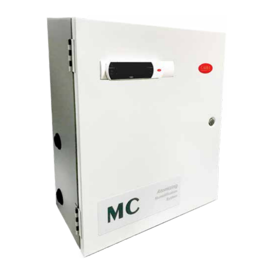
Page 42: Control Cabinet Parts
0-30 PSI GAUGE WATER INSTALLED ON TEE AND REGULATOR ROTATED TO FACE VIEWER VALVE NOT SHOWN Part Number Quantity Part Number Quantity MCPG30 MCSOLSS1/4NO MCPG100 MCBUSPVC1/2SX1/4FPT MCUNIDNPVC1/2S ALNIPSS1/4XC MCBALLVALVEPVC1/2 MCNIPSS1/4X21/2 MCWATEREG1/4 MCTEESS1/4FPT MCSOLSS1/4NC MCELBOWSS1/4FPT MC DUCT +03U400025 - rel. 4 - 20201201... - Page 43 Complete 1/2” water control section - for all types of water MCRSWITCH SP/ST On/Off Rocker Switch MCKPCO5P00 Kit MC Control PCO5+ programmed P+50CON0L0 PCO controller plug in wiring connectors NOTE: Where identified - for parts with Ser.# <2300 - contact Carel USA MC DUCT +03U400025 - rel. 4 - 20201201...
-
Page 44: Wiring Diagrams
8. WIRING DIAGRAMS 8.1 Duct Main / DDC (for reference only - refer to wiring diagram in control cabinet) MC DUCT +03U400025 - rel. 4 - 20201201... -
Page 45: Secondary
Max. inlet water pressure: 125 psi Air consumption: 100 lbs/hr cabinet=15 CFM, 500 lbs/hr cabinet=75 CFM Water consumption: 100 lbs/hr cabinet=0.2 gpm, 500 lbs/hr cabinet=1 gpm Operation: On/Off by humidistat or –Modulating by sensor MC DUCT +03U400025 - rel. 4 - 20201201... - Page 46 MC DUCT +03U400025 - rel. 4 - 20201201...
- Page 48 Agenzia: CAREL INDUSTRIES HQs Via dell’Industria, 11 - 35020 Brugine - Padova (Italy) Tel. (+39) 0499 716611 - Fax (+39) 0499 716600 carel@carel.com - www.carel.com...
Need help?
Do you have a question about the MC and is the answer not in the manual?
Questions and answers