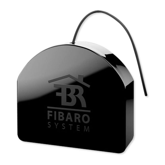
Summary of Contents for FIBARO Smart Module
- Page 1 O P E R A T I N G M A N U A L SMART MODULE (FGS-214) DOUBLE SMART MODULE (FGS-224) v1.0...
- Page 3 Table of contents...
-
Page 4: Important Safety Information
Important safety information Read this manual before attempting to install the device! DANGER OF ELECTROCUTION! Do not modify! Other devices This product is intended for indoor use only in dry locations. Not a toy! IMPORTANT SAFETY INFORMATION... -
Page 5: Description And Features
Description and features Description FIBARO Smart Module and Double Smart Module Main features DESCRIPTION AND FEATURES... - Page 6 Smart Module (FGS-214): Double Smart Module (FGS-224): SPECIFICATIONS...
-
Page 7: Before Installation
Installation Before installation Connecting the device in a manner inconsistent with this manual may cause risk to health, life or material damage. Do not Do not Do not Notes for diagrams: Q/Q1 INSTALLATION... -
Page 8: Electrical Connection
Electrical connection 100-240V AC 24-30V DC S1 S2 SMART MODULE FGS-214 100-240V AC 24-30V DC S1 S2 DOUBLE SMART MODULE FGS-224 INSTALLATION... - Page 9 Adding to Z-Wave network Adding (Inclusion) Adding manually manually: Green Magenta Adding using SmartStart SmartStart using SmartStart: ADDING TO Z WAVE NETWORK...
- Page 10 Green Magenta Removing from Z-Wave network Removing (Exclusion) remove REMOVING FROM Z WAVE NETWORK...
-
Page 11: Operating The Device
Operating the device Controlling channels with inputs Momentary switch (parameter 20 set to 0): Toggle switch without memory (parameter 20 set to 1): Toggle switch with memory (parameter 20 set to 2): Visual indications After powering the device: Update: Menu: OPERATING THE DEVICE... -
Page 12: Resetting To Factory Defaults
Menu Menu Magenta Yellow Resetting to factory defaults OPERATING THE DEVICE... - Page 13 Z-Wave range test To test the main controller’s range: Z-Wave range tester signalling modes: Visual indicator pulsing green Visual indicator glowing green Visual indicator pulsing yellow Visual indicator glowing yellow Visual indicator pulsing violet Visual indicator glowing red Z WAVE RANGE TEST...
- Page 14 Activating scenes Switch Action Scene ID Attribute ACTIVATING SCENES...
- Page 15 Associations Association (linking devices) Smart Module provides the association of 2 groups: 1st association group – “Lifeline” Double Smart Module provides the association of 3 groups: 1st association group – “Lifeline” CONFIGURATION...
- Page 16 Values sent to association groups depending on settings Parameter Parameter Double Click 150/151 152/153 Click Momentary or toggle switches with memory (parameter 20/21 set to 0 or 2) Toggle switches without memory (parameter 20/21 set to 1) CONFIGURATION...
-
Page 17: Advanced Parameters
Advanced parameters Available parameters: Remember relays state Description Parameter size Default value Available values S1 input – switch type Description Parameter size Default value Available values CONFIGURATION... - Page 18 S2 input – switch type Description Parameter size Default value Available values Inputs orientation Parameter size Default value Available values Outputs orientation Only in Double Smart Module Parameter size Default value Available values CONFIGURATION...
- Page 19 Description Parameter size Default value Available values 0x00 0x01 0x02 0x03 Description Parameter size Default value Available values 0x00 0x01 0x02 0x03 CONFIGURATION...
- Page 20 Description Parameter size Default value Available values 0x00 0x01 0x02 0x03 Description Parameter size Default value Available values 0x00 0x01 0x02 0x03 CONFIGURATION...
- Page 21 Description Parameter size Default value Available values 0x00 0x01 0x02 0x03 Description Parameter size Default value Available values S1 input – scenes sent Description Parameter size Default value Available values CONFIGURATION...
- Page 22 S2 input – scenes sent Description Parameter size Default value Available values 150. First channel – operating mode Description Parameter size Default value Available values 151. Second channel – operating mode Only in Double Smart Module Description Parameter size Default value Available values CONFIGURATION...
- Page 23 Parameter size Default value Available values Second channel – reaction to input change in delayed/ 153. auto OFF modes Only in Double Smart Module Description Parameter size Default value Available values First channel – time parameter for delayed/auto OFF 154.
- Page 24 Second channel – time parameter for delayed/auto 155. Only in Double Smart Module Description Parameter size Default value Available values S1 input – Switch ON value sent to 2nd association 156. group Description Parameter size Default value Available values S1 input – Switch OFF value sent to 2nd association 157.
- Page 25 S2 input – Switch ON value sent to 3rd association 159. group Only in Double Smart Module Description Parameter size Default value Available values S2 input – Switch OFF value sent to 3rd association 160. group Only in Double Smart Module...
- Page 26 Q/Q1 output type Description Parameter size Default value Available values 163. Q2 output type Only in Double Smart Module Description Parameter size Default value Available values 164. Lock simultaneous switching of Q1 and Q2 outputs Only in Double Smart Module...
- Page 27 Generic Device Class: Supported Command Classes Command Class Version Secure Z WAVE SPECIFICATION...
- Page 28 Multichannel Command Class (only in FGS-224) Endpoint 1 Generic Device Class: Description: Command Classes: Endpoint 2 Generic Device Class: Description: Command Classes: Z WAVE SPECIFICATION...
- Page 29 Event Parameter Status Type Protection CC Type State Description Hint Assocation groups mapping Association group in Root Endpoint endpoint Z WAVE SPECIFICATION...
- Page 30 Regulations Legal Notices Declaration of conformity WEEE Directive Compliance REGULATIONS...


Need help?
Do you have a question about the Smart Module and is the answer not in the manual?
Questions and answers