
Subscribe to Our Youtube Channel
Related Manuals for Pitney Bowes Relay 5000


Summary of Contents for Pitney Bowes Relay 5000
- Page 1 Shipping & Mailing Inserter Relay ™ 5000/6000/7000/8000 Document Inserting System Operator Guide International English Edition SV63136 Rev. B November 1, 2015...
- Page 2 Pitney Bowes. We have made every reasonable effort to ensure the accuracy and usefulness of this manual; however, we cannot assume responsibility for errors or omissions or liability for the misuse or misapplication of our products.
-
Page 3: Table Of Contents
Table of Contents Safety Information ................v Warning Labels ................vi 1 • System Overview Relay 5000/6000/7000/8000 Inserter Overview ......1-3 Product Features ................ 1-3 System Components ..............1-3 Main Modules ............... 1-3 Additional Modules Available ..........1-3 Control Panel Identification ............1-6 Screen Option Keys .............. - Page 4 Table of Contents Access Rights ................1-19 User Access Levels ............1-19 Log In .................. 1-20 Log Out ................1-20 2 • Display Screen Display Screen Overview ............2-3 Header Area ................2-4 Footer Area ................2-4 Status Area ................2-5 Navigating Options ...............
- Page 5 Table of Contents 4 • Scanning Scanning Overview ..............4-3 Adjusting the Scan Heads ............4-4 Adjusting Scan Heads for Ladder or 2D Orientation Marks .. 4-5 Setting the OMR Scanning Area ..........4-10 Defining the First Mark Position and Code Length ....4-10 Defining the Clear Zone ............
- Page 6 This page is intentionally blank.
-
Page 7: Safety Information
Safety Safety Information Follow these precautions whenever you use your inserting system: • Read all instructions before you attempt to operate the system. • Use this equipment only for its intended purpose. • Place the system close to an easily accessible wall outlet. •... -
Page 8: Warning Labels
Safety • Contact your system supplier for the following: - Supplies - Material Safety Data Sheets - If you should damage the unit - Required maintenance service schedule If Your Stacker has an AC Adapter: • Use the AC power adapter included with this device. Third party adapters may damage the device •... -
Page 9: System Overview
1 • System Overview Contents Relay 5000/6000/7000/8000 Inserter Overview ......1-3 Product Features .................1-3 System Components ..............1-3 Main Modules ................ 1-3 Additional Modules Available ..........1-3 Control Panel Identification............1-6 Screen Option Keys ............... 1-7 Fixed Function Keys .............. 1-7 Machine Action Keys ............. 1-8 Change the Language Display ............1-9... - Page 10 This page is intentionally blank.
-
Page 11: Relay 5000/6000/7000/8000 Inserter Overview
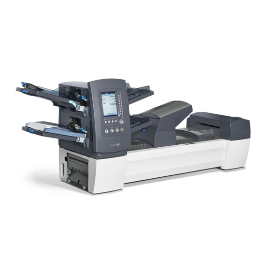
System Overview • 1 Relay 5000/6000/7000/8000 Inserter Overview Relay™ 5000/6000/7000/8000 are high throughput, mail creation systems designed to handle a broad range of applications with minimum operator setup adjustments. These systems have the ability to feed, fold, and insert mail piece components into an outer envelope. The systems generate letters or flats as the final mail piece. - Page 12 1 • System Overview Component Identification Relay 5000/6000 System Relay 7000/8000 only Feeder Tower Trays - feed sheets or inserts to the feeder tower. Feeder Tower - is a two-sided tray holder/material feeder. NOTE: If enabled, the lower left tray is assigned with the letter "A" on the Mail Piece Icon Tree.
- Page 13 System Overview • 1 Pre-fold Accumulator - is a staging area for the material that needs to be collated together and then sent to the folder. Folder - applies one of the available fold types to sheets. Post-fold Accumulator - is a staging area for the folded sheets to meet any inserts that are to be included.
-
Page 14: Control Panel Identification
1 • System Overview Control Panel Identification Reset Counter Help Home Cancel Trial Clear Start Piece Deck Stop LED Status Indicator Screen Option Keys - allow you to define settings for up to 24 jobs that you can store in the system’s memory. These keys also provide the means to edit any of the stored jobs. -
Page 15: Screen Option Keys
System Overview • 1 Screen Option Keys The eight screen option keys correspond to options on the screen, and therefore have no dedicated labels. Use these keys to highlight an item in a displayed pick list and/or to select the associated menu, item, action, or option. -
Page 16: Machine Action Keys
1 • System Overview Machine Action Keys The four machine action keys run the system. Trial Clear Start Stop Piece Deck Start Press this green-colored Start key to begin running the selected job Trial Piece Press Trial Piece to do a test run on your job. One complete mail piece will be prepared. -
Page 17: Change The Language Display
System Overview • 1 Change the Language Display 1. From the Home screen, select Menu. 2. From the Menu screen, select Change Language, a list of available languages displays. 3. If necessary, use the Next and Previous options to view additional languages on the list, and select the appropriate language. -
Page 18: How The System Works
1 • System Overview How the System Works Transport Deck The transport deck accepts material from the feeder tower and moves it through the various modules to produce a finished mail piece. Mail Piece Path Material from the feeder trays comes down the feeder tower in a pre-defined order. -
Page 19: Post-Fold Accumulator
System Overview • 1 Post-fold Accumulator The accumulation of folded sheets exits the folder onto the post-fold accumulator area. Other components of the mail piece, such as a Business reply envelope or a pre-folded insert, are added to the accumulation in the post-fold accumulator area. -
Page 20: System Covers
1 • System Overview System Covers Transport deck covers open to provide access to the rollers in the main paper path. Insertion Area Folder Cover Cover Pre-fold Post-fold Accumulator Accumulator Cover Cover The three covers on the front side of the system open to provide access to the paper release knobs. -
Page 21: Open The Covers
System Overview • 1 Open the Covers Main Transport Deck Cover To open the main transport deck cover: 1. Place your fingers into the slot on the top of the cover. 2. Pull down gently. A security tie keeps the cover within the recommended range of movement. -
Page 22: Paper Release Knobs/Levers
1 • System Overview Paper Release Knobs/Levers There are ten paper release knobs and levers on the front side of the system. Each knob provides the means to turn rollers and move material out of the area in which it stalled. Each paper release lever opens an area of the system and allows you to clear any material that may have stalled. -
Page 23: Feeder Tower
System Overview • 1 Feeder Tower The feeder tower is a two-sided tray holder/material feeder that stands at one end of the unit. Unlocking a latch on the left side of the tower opens it to expose feeder exit and tower transport rollers. This makes it easy to access material that may stop as it exits the tower. -
Page 24: Add-On Modules
1 • System Overview Add-On Modules High Capacity Sheet Feeder (HCSF) The HCSF add-on module attaches to the feed tower end of the system to provide greater upstream volume. The HCSF has two feeder trays and a horizontal transport. Each Feeder Tray holds up to 1000 sheets of 20 lb. (80 gsm) paper. -
Page 25: Flats Sealer
System Overview • 1 Flats Sealer The flats sealer closes the flap, seals the envelope, and sends it on to the next module downstream. The Flats Sealer also contains an envelope edge marker. Flats Sealer Cover 1-17 SV63136 Rev. B... -
Page 26: Vertical Power Stacker
1 • System Overview Vertical Power Stacker The vertical power stacker is a compact, powered, bottom-feed stacker that connects to the output of several inserting systems, including the Relay inserters. Horizontal Belt Stacker Belt Stacker - Letter or Flats The Horizontal Belt Stacker can be used in Right Angled or In Line configuration with the inserters. -
Page 27: Access Rights
System Overview • 1 Access Rights There are two security modes available on the system: • Login Not Required Mode - requires four-digit access code to perform supervisor and manager functions. • Login Required Mode - sets up access levels and requires a user ID and password for all system operator, supervisor, and manager functions. -
Page 28: Log In
1 • System Overview Log In • When the Login Required Mode is enabled, entry of a user ID and password is needed to access the system. • When Login Not Required Mode is enabled, entry of an access code is needed to access restricted functions. -
Page 29: Display Screen
2 • Display Screen Contents Display Screen Overview ............2-3 Header Area ................2-4 Footer Area ................2-4 Status Area ................2-5 Navigating Options ..............2-8 Icons and Letters .................2-9 Envelope Icons ..............2-9 Fold Icons ................2-9 Sheet Icons ................2-10 Insert Icons ................2-11 Feeder Assignment Icons ............ - Page 30 This page is intentionally blank.
-
Page 31: Display Screen Overview
Display Screen • 2 Display Screen Overview The display screen is divided into three major areas: • Header Status • • Footer Home Job: ABC Header Area Run Trial Piece Low Sealant Job Items Select Another Job SwiftStart Menu Status Area Loading Instructions and Pre-Run Adjustments Pieces... -
Page 32: Header Area
2 • Display Screen Header Area The header area has two colored bands that run across the top of the screen: the top blue band, the bottom green band. The left side of the top blue band displays the name of the current screen. Depending on the screen, the Job Name may show on the right side. -
Page 33: Status Area
Display Screen • 2 Status Area The status area displays information about the task(s) you are performing. This area contains any or all of the following: • Mail Piece Icon Tree • Item Orientation • Options • Data across the bottom of the screen (Home screen only) - batch count, piece count, and User ID Mail Piece Icon Tree The Mail Piece Icon Tree gives a road map of icons to visually help guide... - Page 34 2 • Display Screen A feeder assignment letter is placed alongside the icon to indicate the • feeder tray the material is loaded into. Two or more feeder assignment letters alongside a single icon indicate that feeder trays have been linked.
- Page 35 Display Screen • 2 Mail Piece Icon Tree Example In the Mail Piece Icon Tree, each icon displays important information about the mail piece component it represents. The following diagram identifies information conveyed by the icon and how it assists you in loading and running a job.
-
Page 36: Navigating Options
2 • Display Screen Navigating Options The right side of the display screen lists the options and functions available for the current screen. Once you make a selection, more options for that selection display. Refer to the example screens below. Jobs Edit Outer Envelope Job: 123... -
Page 37: Icons And Letters
Display Screen • 2 Icons and Letters The following tables provide descriptions of the various icons you will see on the display screen. Envelope Icons Tower Feeder HCEF* Orientation: flap side down, Orientation: flap side down, flap first. flap last. Non-Window Letter Envelope Window Standard Flap... -
Page 38: Sheet Icons
2 • Display Screen Sheet Icons Orientation: Orientation: Orientation: Orientation: face up, top face up, bottom face down, top face down, first. first. first. bottom first. Sheet, Not Personalized Sheet, Top Address Sheet, Middle Address Sheet, Bottom Address Multiple Sheets, Not Personalized Multiple Sheets, Top Address... -
Page 39: Insert Icons
Display Screen • 2 Insert Icons Orientation: Orientation: Orientation: Orientation: face up, top face up, face down, top face down, first. bottom first. first. bottom first. Slip or Generic Insert Reply Envelope Reply Card Multiple Slips or Generic Inserts Multiple Reply Envelopes Multiple Reply Cards 2-11... -
Page 40: Feeder Assignment Icons
2 • Display Screen Feeder Assignment Icons Feeder assignment is indicated by a letter in a grey square to the right of the job item icon in the Mail Piece Icon Tree. The letter that will display in the blue square depends on the assigned feeder. •... -
Page 41: Run A Job
3 • Run a Job Contents Powering Up ................3-3 Home Screen................3-4 Run a Job ..................3-5 Select a Job ................3-6 Set Up Feeders and Load Material ........3-7 Additional Adjustments ............3-20 Pre-Run Adjustments..............3-21 Feed a Test Envelope ............3-21 Perform Width Adjustments (Outer Envelope Openers) .. - Page 42 This page is intentionally blank.
-
Page 43: Powering Up
Run a Job • 3 Powering Up WARNING! Read the safety information in the front of this guide before connecting the system to power. 1. Connect the power cord to the socket on the back of the inserter. 2. Plug the power cord into a suitable power outlet. Verify the power outlet is near the inserter and is easily accessible. -
Page 44: Home Screen
3 • Run a Job Home Screen When the system completes the startup process, the Home screen displays. The last job run displays on the Home screen. Information about the job displays, along with the ability to select a different job, edit settings for the displayed job, use the SwiftStart feature, and view loading instructions for ™... -
Page 45: Run A Job • 3
Run a Job • 3 Run a Job This section provides the instructions to run or edit a job. The content in this section assumes that the job to be run has been created and is in the Saved Jobs list in your system. If the job does not exist, a Supervisor/Manager must create and save it. -
Page 46: Select A Job
3 • Run a Job Select a Job If the job you want to run displays in the Home screen, proceed to Running a Trial Piece in this chapter. If the desired job does not appear, follow the steps below to select a job: 1. -
Page 47: Set Up Feeders And Load Material
Run a Job • 3 Set Up Feeders and Load Material Once you select the job you want to run, you need to set up the system: • Attach Trays to the Feeder Tower, if prompted • Load Material into the Trays as directed by the Mail Piece Icon Tree and the loading instructions for the selected job. - Page 48 3 • Run a Job 3. Slide the tray into the tray mounts until you feel the tray seat into place. NOTE: The tray is seated properly when the notch on the bottom of each side of the tray is seated in the groove on each of the tray mounts. Notch on Tray Figure 3.1.2: Check Tray Seating Groove on...
- Page 49 Run a Job • 3 Load Material into the Trays Follow the loading instructions before you run a job. The loading orientation may change, depending on the feeder assignment and job settings. For instance, one Feeder may need to be loaded bottom first and another top first.
- Page 50 3 • Run a Job Adjust Tray Side Guides A grooved, blue side guide adjustor is located at the open end of each tray. This adjustor controls the opening and closing of the tray side guides. To open or close the side guides on the feeder tower trays: 1.
-
Page 51: Select A Job
Run a Job • 3 Load a Sheet Tray Sheet trays feed flat, unfolded material. Be sure to keep your stack of materials at or below the fill marks on the tray walls to avoid feed problem NOTE: To view a demo of the sheet tray loading and side guide adjustment processes: go to the Home screen and select Loading Instructions and Pre-Run Adjustments. - Page 52 3 • Run a Job Load Sheets into the HCSF 1. After loosening the pages of the stack of sheets, turn the HCSF tray Side Guide Adjustor counterclockwise to open the Tray wide enough to accommodate the stack of sheets. NOTE: The side guide adjustor is located below the tray indicator letter.
- Page 53 Run a Job • 3 Max fill line HCSF Ready to Feed SV63136 Rev. B 3-13...
- Page 54 3 • Run a Job Adjust the HCSF Guides If the sheet width is different from the sheet width used in the previous job, you need to adjust the HCSF guides for the new job. IMPORTANT: Make sure you enabled the High Capacity Sheet Feeder Trays before performing this adjustment.
- Page 55 Run a Job • 3 5. Set the length guide: a. Pull the length knob (knob 12) straight out. b. Turn the knob to position yellow line on the length guide bar at the trailing end of the sheet. c. Release the length knob once the length guide is properly placed. Yellow line on Length Guide Bar 6.
- Page 56 3 • Run a Job Load Insert Trays Insert tray feed items that do not need folding include envelopes, cards, booklets, slips and pre-folded media. Insert trays have two sets of maximum fill lines - one set for slips, and a second set for envelopes. NOTE: To view a demo of loading the insert tray and adjusting the side guide adjustment processes: go to the Home screen and select Loading Instructions and Pre-Run Adjustments.
- Page 57 Run a Job • 3 Load the High Capacity Envelope Feeder (HCEF) The HCEF holds up to 500 envelopes. To load envelopes into the HCEF, you will need to adjust the side guides, wedge, and separator gap. Before you begin making any adjustments, fan a stack of envelopes and remove any that are nested, curled or damaged in any way.
- Page 58 3 • Run a Job Adjust the HCEF Wedge 1. Insert an envelope into the HCEF with the bottom edge of the envelope against the center guide, in line with the two screws. The top edge of the envelope (edge with flap) should point towards the wedge. NOTE: Ensure the envelope is centered, not angled, on the center guide.
- Page 59 Run a Job • 3 Adjust the HCEF Separator Gap NOTE: Adjust the HCEF Wedge before you can adjust the Separator Gap.. 1. Prepare an envelope for the separator gap adjustment: a. Cut a strip of 20 lb. (80 gsm) paper to fit inside an envelope. b.
-
Page 60: Additional Adjustments
3 • Run a Job 5. Pull the envelope out from the HCEF. Envelopes Lined Up with Tab on Wedge 6. Shingle a .7 to 2-inch (20mm to 50mm) stack of envelopes. 7. Place the envelopes into the HCEF flap side down, flap last. 8. -
Page 61: Pre-Run Adjustments
Run a Job • 3 Pre-Run Adjustments Feed a Test Envelope 1. Load the outer envelopes into the envelope feeder(s). 2. From the Home screen select Loading Instructions> Pre-Run Adjustments> Envelope Opener Settings. NOTE: The system automatically selects the feeder when only one outer envelope is being used. -
Page 62: Perform Width Adjustments (Outer Envelope Openers)
3 • Run a Job Perform Width Adjustments (Outer Envelope Openers) 1. Loosen the thumbscrews on the top of the outer envelope openers. Outer Envelope Opener Thumbscrews 2. Slide the openers as required to align the pointers with the outer edges of the envelope. -
Page 63: Perform Length Adjustments (Inner Envelope Openers)
Run a Job • 3 Perform Length Adjustments (Inner Envelope Openers) 1. If using windowed envelopes, loosen the thumbscrews that secure each inner envelope opener. NOTE: There are three inner envelope openers and these typically need length adjustments only. When needed, these (except the Middle Opener) can be moved laterally. -
Page 64: Verify Settings
3 • Run a Job 3. If necessary, loosen the knob on the insertion edge of the inner envelope opener, and adjust until it goes at least 5 mm into the top panel of the envelope. Insertion Edges of Inner Envelope Openers 4. -
Page 65: Manual Feeder
Run a Job • 3 Manual Feeder The system automatically adjusts for most materials. However, if the throats of your outer envelopes vary significantly, a manual adjustment may be needed. Likewise, if different width or length sheets are fed from a HCSF (High Capacity Sheet Feeder), there are adjustments to be made. -
Page 66: Adjust Manual Lever For Stiff Media Mode (Relay 8000 Only)
3 • Run a Job Adjust Manual Lever for Stiff Media Mode (Relay 8000 Only) Mail pieces with stiff inserts leave the inserter through the flats exit. The Stiff Media feature requires the manual lever (with sensor) to hold the flats gate open. -
Page 67: Run A Trial Piece
Run a Job • 3 Run a Trial Piece When job setup is completed, you must run a trial piece to ensure system function and verify the accuracy of the final mail piece. To run a trial piece: 1. Attach the feeder trays to the feeder tower. NOTE: Highlight the Mail Piece Tree Icons on the Home screen for information on the tray type to use, orientation of the material in the tray, and location of the tray on the feeder tower. - Page 68 3 • Run a Job c. Use the UP/DOWN keys to re-position the address, and then select Finished. You will be returned to the Home screen. d. If you want to make other adjustments, select Edit Job. You will now be able to add, delete, or move mail piece components and to change parameters for a document(s) in the mail piece.
-
Page 69: Review Job Settings
Run a Job • 3 Review Job Settings The Review Job screen provides an at-a-glance view of the settings for each of the mail piece component parameters and the general job settings. This screen is a time efficient way to make sure that you have selected the correct job. -
Page 70: Start The Job
3 • Run a Job Start the Job Once the trial piece is verified, you are ready to start running the job: 1. Verify you are in the Home screen. 2. Press START. The system begins running the job SwiftStart Jobs ™... -
Page 71: Running The Mail Machine Interface
Run a Job • 3 Running the Mail Machine Interface Follow the steps below to process mail using the MMI. 1. Power-up the inserting system. 2. Power-up the mailing system. 3. Ensure that the inserting system has been set up for the job: •... - Page 72 3 • Run a Job 6. Verify the following: • Sufficient funds for the job on the mailing system • MMI is working • Correct mode is set on the mailing system Connect+ Side Guide (without MMI) Clearance Between Envelope and Side Guide 7.
-
Page 73: Adjust Screen Brightness And Contrast
Run a Job • 3 Adjust Screen Brightness and Contrast Follow the steps below to adjust the contrast and/or brightness of the display screen: 1. From the Home screen, select Menu>Tools>Configure System>Set Brightness/Contrast. 2. From the Set Brightness/Contrast screen: • Press the UP/DOWN arrow key(s) to increase/decrease screen brightness. -
Page 74: Set The Time And/Or Date
3 • Run a Job Set the Time and/or Date Follow the steps below to adjust the internal Time and/or Date of the system: 1. From the Home screen, select Menu>Tools>Configure System>Set Date/Time. NOTE: If you are not logged in with supervisor or manager access rights, you will be prompted to enter an access code. -
Page 75: Refill The Sealing Solution
Run a Job • 3 Refill the Sealing Solution A warning message appears on the display screen when it is time to replenish sealing solution in the sealer bottle : To refill the bottle: 1. Open the Sealer bottle cover and remove the bottle from its holder on the system and place it on a flat surface. - Page 76 This page is intentionally blank.
- Page 77 4 • Scanning Contents Scanning Overview..............4-3 Adjusting the Scan Heads ............4-4 Adjusting Scan Heads for Ladder or 2D Orientation Marks ... 4-5 Setting the OMR Scanning Area..........4-10 Defining the First Mark Position and Code Length ....4-10 Defining the Clear Zone............. 4-11 Additional Information ..............4-12...
- Page 78 This page is intentionally blank.
-
Page 79: Scanning Overview
Scanning • 4 Scanning Overview The system offers two types of scanning; both types are optional features: • Optical Mark Recognition (OMR) - uses a dark solid line on a sheet of light colored paper. OMR presents in a "ladder" orientation. Barcode Recognition (BCR) - a series of vertical bars and spaces •... -
Page 80: Adjusting The Scan Heads
4 • Scanning Adjusting the Scan Heads Once the system administrator or system supplier sets up the scan configuration, the key to maximizing barcode or OMR performance lies in proper adjustment/positioning of the scan heads to be able to read the mark. -
Page 81: Adjusting Scan Heads For Ladder Or 2D Orientation Marks
Scanning • 4 Adjusting Scan Heads for Ladder or 2D Orientation Marks 1. Fold one of the sheets to be scanned in half vertically (side with mark facing up.) 2. Draw two arrows, one at the top of the mark, and one at the bottom of the mark, pointing towards the top of the sheet. - Page 82 4 • Scanning 6. Open the tower cover: • If the scanner is in the Feeder Tower (Feeders A, B, C, D) open the feeder tower cover • If the scanner is in the HCSF (High Capacity Sheet Feeder J, K, L, M), open the HCSF tower cover.
- Page 83 Scanning • 4 8. Use the blue thumbwheel to move the scan head. Move the thumbwheel until the pointer lines up with the measurement (distance from the center of the page to the center of the mark) defined earlier. Blue thumbwheel Blue Thumbwheel - Adjust Scan Head Position NOTE: The scanning area on your system may appear different, but operation concepts are the same.
- Page 84 4 • Scanning 9. If additional scan heads are to be used, repeat step 1 to 8 for each. 10. To verify the adjustment is correct: a. From the home screen, select Loading Instructions and Pre-Run Adjustments>Scanner Setup. b. Use the UP/DOWN arrow keys to select a feeder to run. c.
- Page 85 Scanning • 4 7. Determine the direction the Scan Head needs to be moved (to the left or right of 0 on the ruler): • Make sure the center of the sheet (the vertical fold) is lined up with the center of the inserter (at 0 on the ruler.) •...
-
Page 86: Setting The Omr Scanning Area
4 • Scanning Setting the OMR Scanning Area Material is scanned as it feeds through the inserter. This means that the scanner reads a vertical strip or margin down the page, defined by the specifications. The system must be told if the entire margin (the strip down the page that is scanned for marks) is clear of any other printing or punched holes, etc. -
Page 87: Defining The Clear Zone
Scanning • 4 Defining the Clear Zone 1. When requested by the inserter, measure and enter the distance (A) from the top edge of the sheet to the point after the printed matter where you wish the inserter to START scanning. 2. -
Page 88: Additional Information
4 • Scanning Additional Information • Paper weight range for OMR is 18 lb. (70 gsm) to 32 lb. (120 gsm). • Feeder linking will only work correctly if the operator has started with the correct sheet (i.e. linking can only be done reliably on a collation break). - Page 89 5 • Stoppages and Troubleshooting Contents Clear Material Stoppages ............5-3 Clear a Stoppage ..............5-3 Resume the Job ..............5-3 Outsorted Material ..............5-4 Troubleshooting and Self-Help Aides ..........5-4...
- Page 90 This page is intentionally blank.
- Page 91 Stoppages and Troubleshooting • 5 Clear Material Stoppages If a material stoppage occurs, the system immediately stops the job and displays an error message. Follow the instructions on the display screen (removing material that caused the stoppage, resuming the run, and handling the outsorts) to get your system running again.
- Page 92 5 • Stoppages and Troubleshooting Outsorted Material During the recovery from jams and other machine stoppages, the system will automatically clear material from the transport deck that cannot be completed by the inserter. The system counts all mail pieces that it has successfully completed (trial pieces included), but partially assembled pieces are not counted and are transported to the upper divert area.
- Page 93 Stoppages and Troubleshooting • 5 Table 5-1 Startup Problems Problem Cause Action System won’t power up System power cord is not plugged Plug power cord into wall outlet. into the wall outlet. No power at outlet. Check outlet. Verify that wall outlet has power.
- Page 94 5 • Stoppages and Troubleshooting Table 5-3 Tower Feeder Problems Problem Cause Action Failure to feed. Material not within Check that all material meets published specifications. specifications. Refer to Feeder Tower Material Specifications for more information. • Remove curled or warped material. •...
- Page 95 Stoppages and Troubleshooting • 5 Table 5-3 Tower Feeder Problems, continued Problem Cause Action System Double detect is seeing flap or • Set the custom double detect window where there incorrectly seam of insert envelope is no flap, seam or window on the envelope. detects double feeds.
- Page 96 5 • Stoppages and Troubleshooting Table 5-4 Tower Area Problems Problem Cause Action Stoppage in tower Material not within Check that all material meets published specifications. area. specifications, causing Refer to Feeder Tower Material Specifications for more skew. information. • Remove curled or warped material.
- Page 97 Stoppages and Troubleshooting • 5 Table 5-6 Insertion Area/Envelope Flapper Area Problems Problem Cause Action Stoppage in insertion Outer envelope is skewed. Check side guides; incorrect adjustment area or flapper area; can cause skewing. failure to insert. Refer to Adjusting Tray Side Guide for instructions.
- Page 98 5 • Stoppages and Troubleshooting Table 5-6 Insertion Area/Envelope Flapper Area Problems Problem Cause Action Stoppage in Envelope openers insertion area improperly adjusted. or flapper area; (continued) failure to insert. (continued) Recommended distance: .5" .5-inch to 1 inch (15 to (15mm) 25mm) between the tip of the outside finger and the edge...
- Page 99 Stoppages and Troubleshooting • 5 Table 5-6 Insertion Area/Envelope Flapper Area Problems, continued Problem Cause Action • Contents of insertion Adjust the Aligner custom settings: pack are catching on NOTE: If the contents of the insertion pack are thick, side seam inside of and you are having trouble inserting the pack into a small envelope.
- Page 100 5 • Stoppages and Troubleshooting Table 5-7 Moistener/Mail Piece Exit Problems Problem Cause Action No seal, failure to seal, Sealing is off in job set • Check job definition. incomplete seals. • Make sure sealer is ON. Low sealant level. Add water or sealing solution.
- Page 101 Stoppages and Troubleshooting • 5 Table 5-7 Moistener/Mail Piece Exit Problems, continued Problem Cause Action Envelope exit through Collations may be too stiff If the envelope is longer than 6 inches (152mm), letter path is unreliable; to exit through the letter process it through the flat exit path: envelope is damaged.
- Page 102 5 • Stoppages and Troubleshooting Table 5-8 High Capacity Envelope Feeder Problems Problem Cause Action Failure to feed. Envelopes not advancing Push or tap the bottom of the stack of envelopes down Tail Prop. to advance down tail prop. • Separator Gap too Check the separator gap, side guide, and tail tight.
- Page 103 Stoppages and Troubleshooting • 5 Table 5-9 Mail Piece Problems Problem Cause Action Wrong fold type. Job is set up incorrectly. Check job definition and make appropriate adjustments to meet job specifications. Fold panel length incorrect. Job is set up incorrectly. Select auto-measure, or make manual adjustments to meet job specifications, then rerun a trial piece.
- Page 104 This page is intentionally blank.
- Page 105 6 • Maintenance Contents Routine Maintenance..............6-3 Daily Tasks ................6-3 Replace the Moistener Wick ..........6-3 Replace the Moistener Brushes ..........6-5 Replace the Envelope Edge Marker Roller ......6-6...
- Page 106 This page is intentionally blank.
-
Page 107: Routine Maintenance
Maintenance • 6 Routine Maintenance There are several maintenance tasks operators can perform on the system. Be sure to schedule routine service with your system supplier at the appropriate intervals. Daily Tasks • Remove any excess paper dust that has accumulated on or around the system modules. - Page 108 6 • Maintenance 3. Release the plastic latches (one on each side of the reservoir): a. Place the thumb of one hand on the latch at rear of machine (i.e. the latch furthest from you). b. Place index finger of the other hand on other latch (closest to you). c.
-
Page 109: Replace The Moistener Brushes
Maintenance • 6 Replace the Moistener Brushes Replace the moistener brushes when they show wear. Moistener Brushes 1. Open the insertion area cover. 2. Remove old brushes: a. Hold the blue brush holder in place with one hand while you use the other hand to push the bristles of the old brush completely free from the holder. -
Page 110: Replace The Envelope Edge Marker Roller
6 • Maintenance 3. Install the new brushes: NOTE: Avoid bending or deforming the brush bristles; permanent distortion of the bristles will prevent envelopes from sealing correctly. a. Hold the blue brush holder in place with one hand. b. Insert the metal edge of the new brush into the channel opening in front of the brush holder. - Page 111 7• Specifications Contents System Specifications ..............7-3 System Footprint - Dimensions ..........7-3 Component Specifications ............7-4 Component Dimensions ............7-4 Component Capacities ............7-4 Scanning Capability (optional) ..........7-6 Environmental Limits ............. 7-6 Feeder Tower and Base Material Specifications ....7-7 General Information ...............
- Page 112 This page is intentionally blank. SV63136 Rev. B...
-
Page 113: System Specifications
(1537 mm) 118" LOA (2997 mm) NOTES: • System depth is 22.8 in (579 mm) • Drawings are not to scale • All dimensions approximate • The Relay 5000/6000 does not include the High Capacity Envelope Feeder SV63136 Rev. B... -
Page 114: Component Specifications
Component Dimensions Length overall, height Weight, unboxed 89" (2261 mm), 31" (787 mm) 327 lbs. (148 kg) Relay 5000 Inserter 89" (2261 mm). 33.5" (851 mm) 350 lbs. (158 kg) Relay 8000 Inserter High Capacity Sheet 43.5" (1105 mm), 28.6" (726 mm) 150 lbs. - Page 115 Specifications • 7 Folder Fold Types Top address C fold, Z fold, single documents and double fold Bottom address C fold, Z fold and Maximum number of documents single fold sheets per collation: 8 (see Notes below) (20 lb. [80 gsm]) Middle address C fold documents...
-
Page 116: Scanning Capability (Optional)
7 • Specifications High Capacity Envelope Feeder (HCEF) Relay 5000/6000 The HCEF is standard on the Relay 7000/8000 professional series; it is not available for the series. Material Letter-size envelopes Depth: 3.5" (89 mm) to 6.5" (165 mm) Material Dimensions Width: 8.5"... -
Page 117: Feeder Tower And Base Material Specifications
Specifications • 7 Feeder Tower and Base Material Specifications For reliable operation, all materials must conform to published specifications. Feed problems and high stall rates are often due to use of substandard materials. General Information • Material fed for letter-size mail pieces must be capable of being transported through a 1.5 inch (38 mm) radius, 1/4 turn without permanent deformation, breaking of perforations, or any other damage to the mail piece. - Page 118 7 • Specifications Envelope Throat Definitions 5.3 in. (135 mm) Centered at Center Line 4 in. (100 mm) Centered at Center Line *Diagram is not to scale Dimension Value Description 1.6 inch (41 mm) Maximum throat depth measured at the center line of executive style envelopes.
- Page 119 Specifications • 7 Envelope Size for Insertion • Envelopes shall be at least 0.5 inch (13 mm) wider than the sum of the maximum width of the insert pack plus the thickness of the pack. • Envelopes shall be at least 1/4 inch (6 mm) deeper than material to be inserted.
-
Page 120: Inserts
7 • Specifications Inserts Inserts are defined as material that does not require folding (may be pre- folded) before insertion into letter-sized envelopes. This definition includes individual sheets, collations of unfastened sheets, C folded or single folded inserts or pre-made, bound booklets (no fastener exposed that might damage rollers). -
Page 121: Sheets
Specifications • 7 Sheets Sheets refer to material that must be folded before being inserted into standard letter envelopes. In the special case of flats, sheets are not folded. A group of sheets is referred to as a collation. Material Substrates Acceptable paper types include new or recycled bond, text, laser and offset. -
Page 122: High Capacity Sheet Feeder (Hcsf) Material Specifications
7 • Specifications High Capacity Sheet Feeder (HCSF) Material Specifications For reliable operation, all materials must conform to published specifications. Feed problems and high stall rates are often due to use of substandard materials. General Information • Material fed for letter-size mail pieces must be capable of being transported through a 1.5 inch (38 mm) radius, 1/4 turn without permanent deformation, breaking of perforations, or any other damage to the mail piece. -
Page 123: Materials Not Certified For Use
Specifications • 7 Materials Not Certified for Use Contaminants Materials with visible material loss (loose powder, ink, surface glaze, etc.) when hung free over a clean surface and struck sharply with a standard wood ruler should not be used. Special Materials •... - Page 124 This page is intentionally blank.
- Page 126 3001 Summer Street Stamford, CT 06926-0700 www.pitneybowes.com SV63136 Rev. B © 2015 Pitney Bowes Inc. All Rights Reserved...
Need help?
Do you have a question about the Relay 5000 and is the answer not in the manual?
Questions and answers