
Related Manuals for MSB Technology The Reference DAC


Summary of Contents for MSB Technology The Reference DAC
- Page 1 The Reference DAC User Guide Check our website for the most recent user guides, firmware, and drivers: www.msbtechnology.com Technical support email is: techsupport@msbtechnology.com 12.10.2020...
-
Page 3: Technical Specifications
Technical specifications Supported Formats 44.1kHz to 3,072kHz PCM up to 32 bits (Input depedent) 1xDSD, 2xDSD, 4xDSD, 8xDSD Supports DSD via DoP on all inputs Digital Inputs 4x Advanced isolated input module slots XLR Analog Inputs 100K Ohm Balanced 12Vrms Maximum Isolated when not selected XLR Analog Outputs 3.57Vrms Maximum (Digital Input) 12Vrms Maximum (Analog Input) -
Page 4: Setup And Quick Start
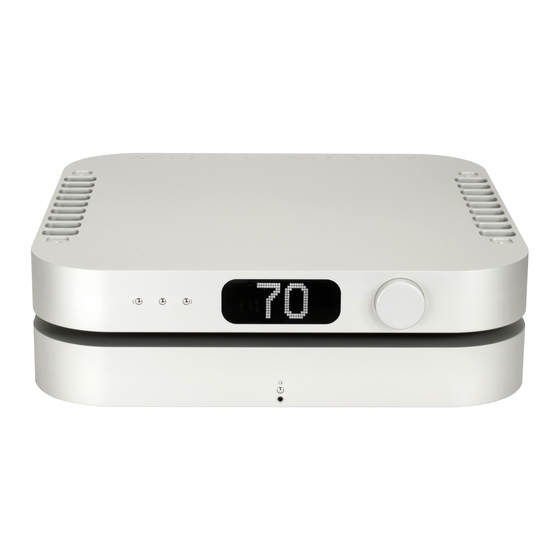
Setup and Quick Start The interface is quite simple with few user controls. Input source defaults on to auto switching. The display will let you know if you have an active input. On power up, the volume is reset to the programmed startup level. -
Page 5: User Interface
User Interface Menu The square button is single purpose. It will enter the Button setup mode at the top of the menu tree. If in the setup, and it doesn’t matter where, this button will exit the setup and return to the normal operational mode. Input The right and left arrows switch inputs. - Page 6 About the 4 input module slots The DAC has four input module slots. They are labeled A through D. There are two classes of input modules, analog and digital. Analog modules must be placed adjacent to the analog output module. They can be either be additional analog inputs or a second analog output module.
- Page 7 Additional Analog Inputs and Outputs In addition to the primary output module, additional analog inputs and a secondary analog output can be added. Isolated Provides a second analog output as single-ended or Analog balanced. Output Only one analog output module can be added per DAC.
-
Page 8: Removing And Installing Modules
BASE OUTPUT MODULE WORD SYNC TOSLINK RIGHT LEFT CHASSIS THE REFERENCE DESIGNED POWERBASE MADE SERIAL 12 VOLT CALIFORNIA RP100001 TECHNOLOGY GROUNDING TERMINALS 105-130. 210-260 VAC TRIGGER POWER 2 POWER 1 Removing and Installing Modules Removal and installation of modules is a completely tool free process that is easily performed at the back of the unit. -
Page 9: Loading New Firmware
The Heart of the System - Preamp and DAC This product is a unique combination of a very high performance DAC and the ultimate passive preamp. For the best possible sound in your system, it should be connected directly to your audio amplifiers. Our preamp philosophy is based on the belief that from the moment analog audio is created, every transition that is made degrades the sound quality. - Page 10 The MSB Remote Indicator LED While in use: White - Command Sent Red and White - Command Sent and Low Battery Red Flashing - Needs Charging While charging: Red - Charging White - Fully Charged Power Powerbase on and off. When the powerbase is linked to an amplifier or MSB product, this button will turn off the entire system (See powerbase manual for details)
-
Page 12: Setup Menu Options
Saving Menu and Startup Settings When changing settings in the menu, use the enter button in the center of your volume wheel on the remote or the right arrow on the DAC faceplate to confirm settings in the DAC menu. After you have made your changes in the DAC menu, use the menu button to exit the DAC menu completely to save the changes you have made in the DAC menu. - Page 13 Setup Menu Continued... Volume This can be adjusted from 0 - 100. This is the default (Startup volume volume the DAC will power up at. If you choose to use the and DSD DAC with a external preamp, we recommend setting the settings) default volume to 98.
- Page 14 Reference Powerbase The powerbase contains isolation technology. The powerbase detects the input voltage and switches to 120 volt or 240 volt operation. It is also available in a fixed 100 volt configuration. All powerbases have over-voltage protection. Two fuses are provided: - 5A 250V SLO BLO - 5 mm x 20 mm miniature fuse (This is the main fuse).
- Page 15 Powerbase Controls There is one button on the front of the powerbase as well as two control features just under the front of the powerbase on the bottom. White - Power on. Red - Power off. indications Amber - Linked mode, 12 volt trigger controlled. Flashing Amber - Over-voltage protection.
- Page 16 Ground Jumper IN - Basic Operation The Basic Operation provides isolation only for the DAC. This gets you half the protection available. Be sure the jumper is in place between the Chassis Ground and Amplifier Ground. This is the shipping configuration. NEVER OPERATE WITHOUT THE JUMPER OR A GROUND WIRE ATTACHED.
- Page 17 Dual Powerbase Grounding Diagram In this configuration you will simply lift the grounding lug jumper and make a connection from the “Amp Ground” lug to either ONE of your mono-block amplifiers or to your single stereo amplifier.
-
Page 18: Technical Support
Technical Support If you are experiencing any issues with your MSB product, please contact your nearest dealer or try our support page at www.msbtechnology. com/support. Please be sure you have the most current edition of your products firmware installed. If your issue persists please feel free to contact MSB directly. - Page 19 The Reference DAC Limited Warranty Warranty includes: • MSB warrantys the unit against defects in materials and workman- ship for a period of 5 years from the date the unit was originally shipped from MSB. • This warranty covers parts and labor only, it does not cover shipping charges or tax/duty.
Need help?
Do you have a question about the The Reference DAC and is the answer not in the manual?
Questions and answers