Table of Contents
Advertisement
Quick Links
Advertisement
Table of Contents

Subscribe to Our Youtube Channel
Summary of Contents for MSB Technology Gold Link Dac III
- Page 2 Thank you for purchasing the world famous LINK DAC III. We are sure you will be very pleased with it. The Gold LINK III includes several new features which signifi- cantly improve performance over the LINK III. At least 100 hours of burn-in is required on this DAC. Customers generally recom- mend one month.
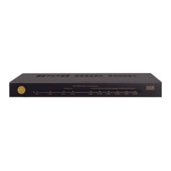
- Page 3 Front Panel The front panel is quite simple with no user controls. LEDs indicate power, the input source, the sampling frequency and whether an option is installed and is active. Power - The blue power LED lights up any time power is applied. The LINK should always be left plugged in with the blue LED lit.
- Page 4 System Configuration Basic Upsampling The toggle switch installed on the rear of the LINK allows upsampling to be turned on or off. The option LED on the front panel indicates “Upsampling on”. The basic upsampling provides a new digitally sampled signal at 96 kHz. This signal is de- coded by the internal LINK DAC at 96K and the 96K LED will also light up ONLY when an active source is being played.
- Page 5 Power Supply Upgrades This is supplied with an outboard desktop power supply. This supply does limit the sonics of the unit and the P1000 Power Base is really recommended . This heavy duty supply is based on a large triple wound toroidal transformer.
- Page 6 Back Panel The back panel contains the interface connectors and one toggle switch. Analog Audio Input - The analog input provides a high quality pass-through switch- ing feature that has many applications. In other words, the pass-through connec- tions are made unless a digital input is active. Active means that the source plugged in is powered on, but not necessarily playing.
- Page 7 MSB N ALANCED NPUT PSAMPLING WITCH ETWORK NPUT 96K U PSAMPLING 132K U PSAMPLING MSB Network Channel Selection The MSB Network supports 4 stereo channels of 192k data at once. Any DAC can be configured to decode any of these 4 channels. For example, when an upgraded DVD player is playing a DTS music CD, one DAC can be configured to Channel 1 and will receive the front channels.
- Page 8 Phase Invert The Phase is normally fixed in the GOLD. It can be changed internally. On the GOLD DAC board a 4 position DIP switch allows several configuration options. The DIP switch position #2 on the GOLD LINK DAC circuit board allows phase invert to be changed.
- Page 9 Analog Filter Change The analog filters in the output stage can be adjusted. The Gold is normally config- ured with the filters disabled. This does not comply with the common practice of rather heavily filtering the outputs to achieve perfect measurements. It is instead set up to sound better, at the expense of perfect measurements.
- Page 10 Operation The operation of the LINK III is fully automatic. The LINK now autoswitches with the following priorities: The balanced input is first, coaxial second, optical third and the analog pass-through is the default condition. The analog pass-through is of very high quality and is great for comparing analog and digital sources.
-
Page 11: Troubleshooting
Troubleshooting No “Source” indicated - Is the 132k upsampling feature on? Is the balanced input active? Both can result in no source LED lit. Next, check for bad cable, or cable plugged into the wrong output on the transport. No sound - Check that source is valid audio source. Change to a standard CD just to be sure. - Page 12 This upgrade installs in most digital products and provides a 192 kHz audio output compat- ible with the LINK III family of DACs. Installs in DVD-A players, standard DVD, CD, LD players as well as DSS systems. All sources are upsampled to 192 kHz. Multichannel output also possible on DTS and Dolby Digital equipped players.


Need help?
Do you have a question about the Gold Link Dac III and is the answer not in the manual?
Questions and answers