Advertisement
Quick Links
Advertisement

Related Manuals for SUNSTONE Ruby Companion Pro


Summary of Contents for SUNSTONE Ruby Companion Pro
- Page 1 Read all instructions before you operate your grill. Save these instructions! Leave this manual To installer or person assembling grill: with grill for future reference. Keep this manual for future reference. To consumer: www.sunstonemetalproducts.com CERTIFIED...
- Page 2 Welcome & Congratulations Congratulations on your purchase of a new Sunstone Ruby Series Companion Pro Grill! We are very proud of our product and we are completely committed to providing you with the best service possible. Your satisfaction is our #1 priority. Please read this manual carefully to understand all the instructions about how to install, operate and maintain for optimum performance and longevity.
- Page 3 INDEX DIRECTORY HAZARDS & WARNING SIGNS ATTENTION: Indicates a potentially hazardous situation which, if not avoided, may result in minor or moderate personal injury, or property damage. WARNING: Indicates an imminently hazardous situation which, if not avoided, will result in death or serious injury.
- Page 4 START-UP CHECKLIST ATTENTION: Never operate the grill unattended. EXPLOSION: When Igniting the Grill – Always keep the Hood Open. “FIRST TIME STARTUP CHECKLIST” Transformer Electrical Plug is properly installed. Installation of the proper gas type and regulator settings. ...
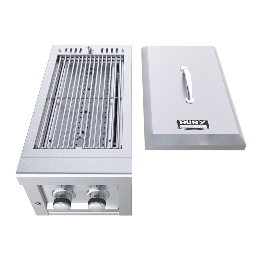
- Page 5 GRILL PARTS– PARTS INDEX PAGE 1 NAME PART NUMBER COVER SUN13CPRO-CO Cover Classic Handle P-HANDLE Drip Pan Tray SUN13CPRO-PAN Electrical Wire Plug P-ELECT-PLUG Burner Large Knob P-KNOB-L LED Light Button P-LIGHT-BUT LED Light Strip SUN13VDB-LED LED Light Support SUN13CPRO-SUP LED Light Casing SUN13CPRO-CAS LED Clip Bracket SUN13CPRO-BRA...
- Page 6 GRILL PARTS – PARTS DIAGRAM PAGE 2...
-
Page 7: Gas Line Connection
GRILL INSTALLATION – STEP BY STEP GUIDE PAGE 3 : Use only with a Ground-Fault Circuit Interrupter - GFCI protected Outlet LIVE CIRCUIT with this Grill. : Use only extension cords approved for outdoor use marked with W-A VOLTAGE Certifications and rated for the power of this appliance. 1. - Page 8 GRILL INSTALLATION – STEP BY STEP GUIDE PAGE 4 4. Slide Grill in Place The grill is specially designed with an internal built in hanger lip located at the Right, Left and Back sides. The grill lip allows it to hang by the three supported edges on the right, left and back.
- Page 9 PAGE 5 GRILL INSTALLATION – PRODUCT DETAILS Technical Measurements If you are installing grill into cabinet structure you may need to refer to these engineer dimensions specifically the grill firebox dimensions. (Measurements were obtained from engineer drawing. margin of error is within 1/8” to actual product) Firebox Size –...
- Page 10 GRILL INSTALLATION – CUT-OUT DETAILS PAGE 6 : Never build an enclosure under the Grill or partition side walls, the Grill ATTENTION must be Free Hanging supported by the countertop only! Must have clear access to underside of Grill within reach of at least Two Vents. Countertop Slide-in Installation (A) Grill Cut-out Depth ------------------------------------------------------------------ 22”...
- Page 11 GRILL INSTALLATION – OVERHEAD STRUCTURE PAGE 7 Overhead Structure Definition: Structure built above Appliance that is sometimes attached to the home’s exterior outside wall or roof and there is a Minimum of “Two” adjacent sides which are open with outside exposure. ATTENTION: All Gas Grill Installations MUST HAVE MINIMUM TWO AIR-FLOW VENTS, either in ELEVATED POSITION for Natural Gas or LOWERED POSITION for Liquid Propane.
- Page 12 GRILL INSTALLATION – ENCLOSED INSTALLATION PAGE 8 Clearances to Combustible Construction: Minimum of 24” from the sides and rear of grill must be maintained to adjacent vertical combustible construction, above the countertop level. You should take in account that there is a large volume of heat, and smoke will exhaust from the rear of the grill.
- Page 13 GRILL INSTALLATION – ENCLOSED INSTALLATION PAGE 9 Enclosed Installation Definition: Structure built above Appliance that is attached to the home’s exterior outside wall, roof or is inside a separate structure like outdoor room and there is a Minimum of “One” Side open with outside exposure. ATTENTION: All Gas Grill Installations MUST HAVE MINIMUM TWO AIR-FLOW VENTS, either in ELEVATED POSITION for Natural Gas or LOWERED POSITION for Liquid Propane.
- Page 14 GAS SETUP – INSTALLATION OVERVIEW PAGE 10 CAUTION: Gas conversion kits are available from Customer care by dialing 888-934-9449. When ordering gas conversion kits, have the model number, and the type of gas (natural or LP) ready. Use only the gas pressure regulator supplied with this appliance. This regulator is set for an outlet pressure of 11 inches water column.
- Page 15 GAS SETUP – LARGE CAPACITY LP TANKS PAGE 11 ATTENTION: If you have a Side Yard Propane Tank, you MUST have additional Medium Pressure Regulator located at the Grill. If you do not serious bodily harm may result or damage to the grill and island structure from HIGH Heat.
-
Page 16: Follow Instructions
GAS SETUP – MEDIUM CAPACITY LP TANKS PAGE 12 Medium Capacity LP Tank The Type 1 connection system has the following features: The system will not allow gas to flow until a positive connection has been made. NOTE: The cylinder control valve must be turned off before any connection is made or removed. - Page 17 GAS SETUP – NATURAL GAS INSTALLATION PAGE 13 NG Gas Hook-up The Natural Gas grill is designed to operate on Natural Gas ONLY, at a pressure regulated at 7”water column (W.C.) equipped with the correct natural gas orifices on the valves and a NG medium pressure regulator on the supply line located near the grill and regulated at the residential meter.
-
Page 18: Grill Start-Up - Lighting The Grill
GRILL START-UP – LIGHTING THE GRILL PAGE 14 REMOVE COVER WHEN LIGHTING THE GRILL & OPEN REMOVE COVER & OPEN VENT BACK VENT PANEL 1. Ensure Grill Control Knobs are In the OFF position, turn either KNOB to High Position. 2. - Page 19 PAGE 15 GRILL START-UP - TROUBLE SHOOTING Q. LED Light is not functioning Likely your LED Light has malfunctioned due to the grill being overheated, or there may be a loose wire on the internal control circuit board. You can access these components by sliding the grill out from your island approx.
-
Page 20: Grill Warranty
6. The cost of service calls to diagnose trouble; or Removal or re-installation cost. This warranty applies to the original purchaser with invoice or proof of purchase and covers Sunstone products intended for personal, family or household usage only. It does not apply to surface rust, corrosion, oxidation or discoloration, which may occur due to moisture or overheating, unless the affected component becomes inoperable.
Need help?
Do you have a question about the Ruby Companion Pro and is the answer not in the manual?
Questions and answers