Table of Contents
Advertisement
Quick Links
Advertisement
Table of Contents

Subscribe to Our Youtube Channel
Related Manuals for GASER SUPER-MAXI


Summary of Contents for GASER SUPER-MAXI
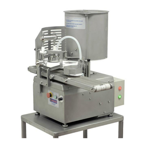
- Page 1 HAMBURGER FORMING MACHINE Mod. SUPER-MAXI...
-
Page 2: Table Of Contents
INDEX 1. INDUSTRIAS GASER ..................... 4 2. EC DECLARATION OF CONFORMITY ..............5 3. HYGIENE CERTIFICATE ..................6 4. INTRODUCTION ..................... 7 4.1 Safety ........................ 7 4.2 Hygiene ......................7 5. TECHNICAL SPECIFICATIONS ................8 6. RECEIPT AND START-UP ..................9 6.1 Receipt ...................... - Page 3 10.8 Safety mechanism overview ................38 10.9 Ejector overview .................... 39 10.10, Paper dispenser overview ................41 11. HAMBURGER FORMERS ................... 42 11.1 Standard shape....................42 11.2 Single shape (on request) ................42 11.3 Mini-double shapes (on request) ..............42 11.4 Special shapes (on request) ................
-
Page 4: Industrias Gaser
SIMPLER, MORE EFFECTIVE AND MORE ECONOMICAL TECHNIQUE. In the 1990s, INDUSTRIAS GASER expanded into markets in various countries around the world, and not just in the hamburger sector. We are aware that our work would be of no value without the trust of our existing clients and partners or the interest shown by those who wish to join them. -
Page 5: Ec Declaration Of Conformity
It is forbidden to make any change or modification to the machine without the prior written permission of our technical department. Use of the machine in these conditions could cause accidents, in which case INDUSTRIAS GASER S.L. accepts no liability for the improper use of the machine. Salt, CARLOS GARGANTA SERRAMITJA TECHNICAL DIRECTOR INDUSTRIAS GASER S.L. -
Page 6: Hygiene Certificate
* Plastic material: polyethylene terephthalate (PETP), white, density 1.37 g/cm Manufactured in accordance with DIN 50014. * Stainless steel: AISI 304, manufactured in accordance with European regulations EN-10088, Chemical composition: C≤0.07% Si≤0.75% Mn≤2% Cr=18-19% Ni=8-10% Salt, CARLOS GARGANTA SERRAMITJA TECHNICAL DIRECTOR INDUSTRIAS GASER S.L. -
Page 7: Introduction
Any use other than the specified one will involve risk for the user and for the machine. INDUSTRIAS GASER S.L. accepts no liability either for damage to the machine or personal injury or injury to third parties that this use might cause. -
Page 8: Technical Specifications
5. TECHNICAL SPECIFICATIONS Table-top machine Can be dismantled for ease of cleaning Easy maintenance Made from stainless steel and plastics suitable for use with food Frequency inverter Atmospheric-air patty ejection Capable of placing paper on one side Patented system 800 m output belt Produces round hamburgers of 50 to 120 mm diameter and other shapes (these must be concentric with a circle and of the measurements mentioned above) Maximum thickness 25 mm with interchangeable moulds... -
Page 9: Receipt And Start-Up
2. It is important that when the machine starts working, it is completely clean to ensure it works properly. 3. The SUPER-MAXI model hamburger former runs on single phase 220 V 50 Hz electrical current. 4. When working on the machine, whether for maintenance, cleaning or any other situation, the machine must be fully disconnected from the electricity supply. -
Page 10: Notes
the START button is kept depressed (Pos. 2, general overview). This function is for adjustment and testing. Press the START button (Pos. 2, general overview) and adjust the speed using the speed control (Pos. 3, general overview) from 1 to 10. The red pilot light will go off and the green one will remain illuminated. -
Page 11: Compacting
6.3.2 Compacting The machine leaves the factory set up for standard compacting. However, as all mixtures are different, for the first 3 or 4 patties, we recommend using the manual button and checking whether they come out with too much or too little mixture. If they do, the compacting will have to be adjusted. - Page 12 To centre the paper on the patties, the position of the dispenser can be adjusted by moving the length and height control (Pos. 5, Paper dispenser overview) and the thickness control (Pos. 3, Paper dispenser overview). The height of the dispenser above the belt at its low position must be 5 mm less than the thickness of the patties.
-
Page 13: Cleaning
7. CLEANING When you have finished using the machine, it must be cleaned. To do so, follow these steps: 1. First of all, ensure the machine is fully disconnected from the power supply. Next, disassemble the machine. 2. Remove the blower tube (Pos. 17, chassis overview). Only the part in contact with the ejector unit (Pos. - Page 14 Remove the ejector unit (Pos. 11, overview) and the paper dispenser unit (Pos. 12, overview). Before doing so, remove the “safety screw” (Pos. 7, ejector overview) from the former unit. Image 6, Extracting safety screw Image 7, Ejector unit removal Image 8, Dispenser unit removal 5.
- Page 15 6. Remove the vanes (Pos. 9, tank overview), loosening the shaft screw (Pos. 13, tank overview) by turning it clockwise. Image 13, Removing safety screw Image 14, Removing vanes 7. Extract the 3 knobs (Pos. 14, tank overview) from the machine and remove the protection (Pos. 8, various overview).
- Page 16 9. Remove the former plate (Pos. 2, former shaft overview). Image 20. Removing former unit Remove the compactor unit (Pos. 4. overview). Image 21. Removing compactor unit Finally, remove the conveyor belt unit (Pos. 6, overview) so that you can clean the belt (Pos. 18, belt overview).
- Page 17 Image 24, Conveyor belt unit removal Image 25, Conveyor belt removal Clean the disassembled components (except for the conveyor belt) with pressurised water and dry well, if possible with air. Clean the machine’s chassis with a damp cloth. Never clean it with pressurised water.
-
Page 18: Maintenance
8. MAINTENANCE This machine requires virtually no maintenance. Even so, there are a few details that must be taken into consideration. Periodically check the condition of all moving parts: retainers, seals, gears and bearings. Periodically check the condition of the gear motor. Periodically check the condition of the safety elements. -
Page 19: Troubleshooting
9. TROUBLESHOOTING The table below lists the problems that might occur with the machine, their potential causes and how to solve them. Problem Cause Solution See manual “6.2. Start-up”, point XX Machine unplugged The machine does not start The safety elements have not been fitted Fit safety elements. - Page 20 The ejector shaft and guides do not have enough oil. Oil the points indicated in the instructions. The ejector does not eject the patties. The ejector counterweight is not attached. Hook on the counterweight. The air tube is not connected. Check whether the air tube is properly connected.
-
Page 21: General Diagram
10. GENERAL DIAGRAM 10.1 Overview Number Description Reference Units CHASSIS UNIT S1010000-E FORMER UNIT S1020000-E TANK UNIT S1030000-E COMPACTOR UNIT S1110000 GENERAL OVERVIEW S1000000-E BELT UNIT S1140000 SAFETY MECHANISM UNIT S1150000 EJECTOR UNIT S1170000 PAPER DISPENSER UNIT PLEASE CONSULT Figure 1, Overview -21-... -
Page 22: Chassis Overview
10.2 Chassis overview Ref. S1010000-E Position Description Reference Units CHASSIS S1010100-E COMPACTOR COLUMN S1100300-E COMPACTOR GUIDE S1100900 DETECTOR SUPPORT S1011100-E S-M DETECTOR SUPPORT COVER S1011200-E HEIGHT ADJUSTER S1101400-E DISPENSER ARM GUIDE S1190600-E MOTOR BODY SUPPORT S1010400-E EJECTOR RAMP SUPPORT S1010500-E COUNTERWEIGHT CORD PULLEY S1010700-E EJECTOR RETURN COUNTERWEIGHT... - Page 23 Figure 2, Chassis overview -23-...
-
Page 24: Former Shaft Overview
10.3 Former shaft overview Ref. S1020000-E Position Description Reference Units COMPLETE FORMER BEARING HOUSING SS910000-E FORMER PLEASE CONSULT TOOTHED FORMER WHEEL S1020300 COMPACTOR CAM S1101100 CAM SUPPORT RING S1021800 FORMER SHAFT NUT S1021500-E VISOR CLAMPING WASHER S1022000-E FORMER SHAFT WASHER S1022400-E *Formers available in different diameters and thicknesses, information on request. -
Page 25: Overview Complete Former Bearing Housing
1 Overview complete former bearing housing Ref. SS910000-E Position Description Reference Units FORMER BEARING HOUSING S1020400-E RETAINER HOUSING S1030600 MECHANICAL FUSE S1200000-E FORMER UNIT SHAFT S1020200 AXIAL BEARING 25-42-11 SI0509115 FORMER SHAFT CORE S1021900-E BEARING SI0109CI255215 RETAINER SI0209R254707 PLATE SUPPORT WASHER S1022200 FORMER BOX SPACER S1021400... -
Page 26: Mechanical Fuse Overview
10.3.1.1 Mechanical fuse overview Ref. S1200000-E Position Description Reference Units LOCATING RING S1020500-E BREAKAGE DETECTION WASHER S1022300-E STAINLESS SCREW M3 × 20 DIN963 FE0108M030200963 2 STAINLESS HEX LOCK NUT M3 DIN985 FE0108M030000985 2 Figure 5, Mechanical fuse overview -26-... -
Page 27: Tank Overview
10.4 Tank overview Ref. S1030000-E Position Description Reference Units COMPLETE TANK BEARING HOUSING SBE SS910000-SBE TANK TOOTHED WHEEL S1030300 TANK BASE S1030100-E TANK BASE SUPPORT S1030500 TANK VANES BEARING S1030700 VANE CENTRAL CORE S1035800 TANK SUPPORT COLUMNS S1030900 TANK S1031000-E VANES S1031300-E SLOT PROTECTION COVER... - Page 28 Figure 6, Tank overview -28-...
-
Page 29: Overview Complete Tank Bearing Housing
10.4 Overview complete tank bearing housing Ref. SS910000-SBE Position Description Reference Units LOWER BEARING HOUSING TANK S1035400 TANK BOX SPACER S1037000 TANK UNIT SHAFT S1035200 BEARING SI0109CI255215 AXIAL BEARING 25-42-11 (FE) SI0509115 RETAINER SI0209R255207 STAINLESS CIRCLIP E-52 DIN472 SI0109I520472 STAINLESS CIRCLIP E-25 DIN471 SI0109E25471 Figure 7, Complete tank bearing housing overview -29-... -
Page 30: Gear Motor
10.4.2 Gear motor Ref. SS970000-E Position Description Reference Units MOTOR EL1420M150B14 GEAR SI0525BR03019120 1 Figure 8. Gear motor overview -30-... -
Page 31: Connecting Rod Overview
10.4.3 Connecting rod overview Ref. S1130000-E Position Description Reference Units CRANK CORE S1130100-E CRANK LOCATING RING S1130200 CRANK-GEAR SPACER S1130400-E Figure 9. Crank overview -31-... - Page 32 10.5 Compactor overview S1100000-E Position Description Reference Units PATTY SUPPORT S1100100-E PATTY COMPACTOR S1100200-E COMPACTOR SHAFT S1100800-E CAM SENSOR S1101000-E COMPACTOR STOP S1100600 STAINLESS HEX. NUT THIN M8 DIN 439 FE0108M100000936 1 COMPACTOR PIN S1101200-E STAINLESS HEX. NUT THIN M-12 DIN 439 FE0108M120000439 2 COLUMN LINK S1101300-E...
-
Page 33: General Overview
10.6 General overview Ref. S1000000-E Position Description Reference Units EMERGENCY STOP BUTTON. SS530000 GREEN PUSH BUTTON SS510000 POTENTIOMETER EL102010KM22 MAGNETIC SWITCH EL2020BNS120 ORANGE 8 POLE MALE CONNECTOR EL0220C08PM AIR PUMP UNIT S1110000-E ELECTRICAL CABINET UNIT S1250000-E PROTECTION S1160400-E STANDARD KNOB S1000300 EJECTOR STICKER PA0230EMAXI... - Page 34 Figure 1, General overview 1 -34-...
-
Page 35: Electrical Cabinet Overview
10.6.1 Electrical cabinet overview Ref. S1250000-E Position Description Reference Units STAINLESS APD CABINET EL0220APD203016 4mm2 WDU TERMINAL EL0220BWDU4 4mm2 EARTH TERMINAL EL0220BWPE04 ORANGE 8 POLE FEMALE CONNECTOR EL0220C08PH SINGLE PHASE PLUG EL0220CEM CIRCUIT BREAKER 2A “C” 1P EL0402MGI02A CIRCUIT BREAKER 10A “C” 1P+N EL0402MGIN10A M20 METAL GLAND NUT EL0808M20... -
Page 36: Air Pump Overview
10.6 Air pump overview Ref. S1110000-E Position Description Reference Units AIR PUMP BODY S1110100-E AIR PUMP UPPER COVER S1110200-E AIR PUMP PISTON S1110300-E ROD SUPPORT S1110400-E PISTON SLEEVE EC030100 ROD/AIR PUMP CONNECTION SHAFT S1110600-E AIR PUMP AIR OUTLET TUBE S1110700-E STAINLESS WASHER M10 DIN125 FE0108M100000125 2 LEVER SPACER... -
Page 37: Belt Overview
10.7 Belt overview Ref. S1140000-E Position Description Reference Units FIXED BELT CHASSIS S1140100-E CHASSIS BELT CONNECTION GUARDRAIL 30140300-SP INTERIOR BELT SHAFT BUSHING 00040600 BELT SHAFT BUSHINGS SUPPORT 00040700 INNER BELT TENSIONING ROLLER AXLE 00040500 MOVABLE BELT CHASSIS S1140200-E BELT DRIVE SHAFT S1146000-E BELT ARTICULATION SHAFT 30140500... -
Page 38: Safety Mechanism Overview
10.8 Safety mechanism overview Ref. S1150000 Position Description Reference Units LIMIT SWITCH SUPPORT S1150300 MOELLER LS-11 LIMIT SWITCH EL0220LS11 STAINLESS CIRCLIP E-15 DIN471 SI0109E150471 STAINLESS WASHER M4 DIN125 FE0108M040000125 4 STAINLESS HEX LOCK NUT M4 DIN985 FE0108M040000985 4 STAINLESS ALLEN SCREW M4 × 35 DIN912 FE0108M040350912 4 STAINLESS HEX SCREW M6 ×... -
Page 39: Ejector Overview
10.9 Ejector overview Ref. SS960000-E Position Description Reference Units EJECTOR SUPPORT S1170200-E EJECTOR SHAFT SUPPORT S1170300-E EJECTOR PLEASE CONSULT EJECTOR SHAFT S1170400-E WHEEL AXLE S1170500-E EJECTOR UNIT UPPER WEIGHT S1170600-E EJECTOR MECHANISM SHAFT PIN S1170800-E THIN EJECTOR SPACER S1171400-E LIFTING RAMP ROLLER S1170900-E THICK EJECTOR SPACER S1171500-E... - Page 40 Figure 17. Ejector overview -40-...
-
Page 41: Paper Dispenser Overview
10.10, Paper dispenser overview Ref. PLEASE CONSULT Position Description Reference Units DISPENSER SUPPORT ARM S1190100-E PAPER DISPENSER SUPPORT PLEASE CONSULT WIDTH SLOT S1190300-E DISPENSER ROLLER S1190500-E LENGTH AND HEIGHT SLOT S1190400-E DISPENSER ROLLER SCREW S1190700-E DISPENSER WEIGHT PLATE PLEASE CONSULT GEAR END WASHER 40000500 Figure 18. -
Page 42: Hamburger Formers
11. HAMBURGER FORMERS 11.1 Standard shape 11.2 Single shape (on request) 140 mm-diameter paper dispenser120 mm-diameter paper dispenser 11.3 Mini-double shapes (on request) 140 mm-diameter paper dispenser120 mm-diameter paper dispenser -42-... -
Page 43: Special Shapes (On Request)
11.4 Special shapes (on request) Any single or double shapes hat fits inside an 18 mm-diameter circle -43-... -
Page 44: Wiring Diagrams
13. WIRING DIAGRAMS -44-... - Page 45 +AR1/2 F26_Gaser Empresa GASER Obra: SUPER MAXI VER 01 CTRA, BESCANÓ, 15 Calle Referencia: CP/Localidad POL. TORRE MIRONA 17190 CP/Localidad Teléfono +34 972 23 65 72 Teléfono +34 972 23 63 66 E-mail gaser@gaser.com E-mail Nombre de proyecto Lugar de instalación Descripción de proyecto...
- Page 46 +DI1/1 L 23AVca L1 23AVca N 23AVca N1 23AVca / 2.0 3x1,5 mm² Cuadro Eléctrico Int. General 0,75 0,75 0,75 Chasis Máquina Verde Control Marcha Velocidad -CN1 0,75 0,75 0,75 Rojo Paro -VF1 SV004iES-1C Frequency Transverter 200-230Vca -CN1 1/2HP -CN1 SV004iES-1C -CN1 Chasis...
Need help?
Do you have a question about the SUPER-MAXI and is the answer not in the manual?
Questions and answers