Table of Contents
Advertisement
Quick Links
Advertisement
Table of Contents

Related Manuals for GASER Super


Summary of Contents for GASER Super
- Page 1 HAMBURGER FORMING MACHINE Mod. SUPER...
-
Page 2: Table Of Contents
INDEX 1. INDUSTRIAS GASER ..................... 3 2. EC DECLARATION OF CONFORMITY ..............4 3. HYGIENE CERTIFICATE ..................5 4. INTRODUCTION ..................... 6 4.1 Safety ........................ 6 4.2 Hygiene ......................6 5. TECHNICAL SPECIFICATIONS ................7 6. RECEIPT AND START-UP ..................8 6.1 Receipt ...................... -
Page 3: Industrias Gaser
SIMPLER, MORE EFFECTIVE AND MORE ECONOMICAL TECHNIQUE. In the 1990s, INDUSTRIAS GASER expanded into markets in various countries around the world, and not just in the hamburger sector. We are aware that our work would be of no value without the trust of our existing clients and partners or the interest shown by those who wish to join them. -
Page 4: Ec Declaration Of Conformity
It is forbidden to make any change or modification to the machine without the prior written permission of our technical department. Use of the machine in these conditions could cause accidents, in which case INDUSTRIAS GASER S.L. accepts no liability for the improper use of the machine. Salt, CARLOS GARGANTA SERRAMITJA TECHNICAL DIRECTOR INDUSTRIAS GASER S.L. -
Page 5: Hygiene Certificate
* Plastic material: polyethylene terephthalate (PETP), white, density 1.37 g/cm Manufactured in accordance with DIN 50014. * Stainless steel: AISI 304, manufactured in accordance with European regulations EN-10088, Chemical composition: C≤0.07% Si≤0.75% Mn≤2% Cr=18-19% Ni=8-10% Salt, CARLOS GARGANTA SERRAMITJA TECHNICAL DIRECTOR INDUSTRIAS GASER S.L. -
Page 6: Introduction
Any use other than the specified one will involve risk for the user and for the machine. INDUSTRIAS GASER S.L. accepts no liability either for damage to the machine or personal injury or injury to third parties that this use might cause. -
Page 7: Technical Specifications
5. TECHNICAL SPECIFICATIONS Tabletop machine Can be dismantled for ease of cleaning Easy maintenance Made from stainless steel and plastics suitable for use with food Frequency converter Capable of placing paper on one side Produces round patties of 30 to 120 mm diameter and other shapes (these must be concentric with a circle and of the measurements mentioned above) Weight controllable with a maximum patty thickness of 25 mm Produces 20 to 60 patties/minute... -
Page 8: Receipt And Start-Up
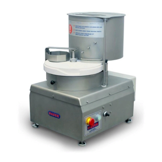
Image 1. Main parts 2. It is important that when the machine starts working, it is completely clean to ensure it works properly. 3. The SUPER model hamburger forming machine works on single phase 220 V 50 Hz electrical current. - Page 9 4. Before starting production, if it has not been calibrated previously, the thickness of the patty must be calibrated. To do so, follow these steps: 4.1. Pull on the latch (Pos. 8, external weight control overview) to expose the calibration gears (Pos.
- Page 10 (Pos. 2, former shaft overview) are exposed. Once the desired weight has been found, select the automatic mode and press the green start button again. Image 4, Position of the plate 7. If the patties are seen to come out with a layer above the plate or they are not well compacted, this can be adjusted using the weight calibration gear.
-
Page 11: Notes
6.3 Notes 6.3.1 Changing patty shape To change the shape of the patties, first disassemble the machine as shown in point “7 CLEANING”. Once the machine has been disassembled, you can change the shape of the patties and reassemble the machine by reversing the order of disassembly. Remember that when you change the shape, the weight might vary. -
Page 12: Cleaning
7. CLEANING When you have finished using the machine, it must be cleaned. To do so, follow these steps: 1. First, remove the paper dispenser unit, keeping it as horizontal as possible when lifting it. Image 9, Removing paper positioner 2. - Page 13 Image 12, Turning tank clockwise Image 13, Removing tank 3. Remove the vanes (Pos. 16, tank overview), loosening the safety screw (Pos. 9, tank overview) by turning it clockwise. Image 14, Removing safety screw Image 15, Removing vanes 4. Next disassemble the base of the tank (Pos. 3, tank overview). The two knobs must be removed (Pos.
- Page 14 5. Finally, remove the former (Pos. 2, former shaft overview) by loosening the former shaft nut (Pos. 5, former shaft overview). Image 16. Removing former shaft nut Image 17. Removing former unit Clean the disassembled components with pressurised water and dry well, using compressed air if possible.
- Page 15 8. MAINTENANCE This machine requires virtually no maintenance. Even so, there are a few details that must be taken into consideration. Periodically check the condition of all moving parts: retainers, gears and bearings. Periodically check the condition of the extractor slice thread (Pos. 12, overview). If it is necessary to change the thread, to remove it, bend the slice, then you can easily remove the thread and replace it with a new one.
-
Page 16: Troubleshooting
9. TROUBLESHOOTING The table below lists the problems that might occur with the machine, their potential causes and how to solve them. Problem Cause Solution See manual “6.2. Start-up”, point 3 Machine unplugged The machine does not start The safety elements have not Fit safety elements been fitted Safety sensors have come lose. -
Page 17: General Diagram
FE0108M060160084 2 DIN84 STAINLESS CHEESE HEAD SCREW M6 × 20 FE0108M060200084 2 DIN84 EXTRACTOR SLICE S1000100 POTENTIOMETER EL102010KM22 EMERGENCY STOP SS530000 GREEN PUSH BUTTON SS510000 TEARDROP TYPE GASER BRAND STICKER PA0230GGASER GASER BRAND STICKER PA0230SUPER BASIC/SUPER/MAXI TANK STICKER PA0230TSUPER -17-... - Page 18 Figure 1, Standard overview 1 Figure 2, Standard overview 2 -18-...
-
Page 19: Chassis Overview
10.2 Chassis overview Ref. S1010000 Position Description Reference Units CHASSIS S1010100 MOTOR SUPPORT S1010400-E LIFTING RAMP S1020900 STAINLESS HEX NUT M10 DIN934 FE0108M100000934 5 STAINLESS STEEL/RUBBER FOOT D-40 SI0226PID40M10 STAINLESS HEX SCREW M10 × 12 DIN933 FE0108M100120933 2 STAINLESS HEX SCREW M6 × 12 DIN933 FE0108M060120933 8 STAINLESS HEX LOCK NUT M6 DIN985 FE0108M060000985 1... - Page 20 Figure 4, Chassis overview 2 -20-...
-
Page 21: Former Shaft Overview
10.3 Former shaft overview Ref. S1020000 Position Description Reference Units FORMER BEARING HOUSING UNIT SS910000 FORMER Ø100 S1020100 FORMER Ø118 S1020100-118 FORMER Ø50 S1020100-50 CAM PLATE S1020600 FORMER TOOTHED WHEEL S1020300 FORMER SHAFT NUT S1021500 EJECTOR SUPPORT S1020700 STAINLESS WASHER M8 DIN125 FE0108M080000125 3 STAINLESS HEX SCREW M8 ×... -
Page 22: Overview Complete Former Bearing Housing
10.3.1 Overview complete former bearing housing Ref. SS910000 Position Description Reference Units FORMER SHAFT CORE S1021900 FORMER UNIT SHAFT S1020200 FORMER CENTRING RING S1020500 RETAINING SEAL SI0209R254707 E-52 DIN472 STAINLESS CIRCLIP SI0109I520472 BEARING SI0109CI255215 FORMER BOX SEPERATOR S1021400 AXIAL BEARING SI0509115 FORMER LOWER BEARING HOUSING S1020400... -
Page 23: Tank Overview
FE0108M040167991 1 DIN7991 STAINLESS HEX SCREW M8 × 25 DIN933 FE0108M080250933 2 GEAR MOTOR SS970000 TANK LOWER SLEEVE B-S S1032900 BASIC AND SUPER SHAFT WASHER S1021700 TANK ATTACHMENT BOLT S1032800 LOWER COLUMN WASHER S1032300 PENNANT PIVOT S1033100 PLATE SUPPORT ARM... - Page 24 Figure 7, Tank overview 1 -24-...
- Page 25 Figure 8, Tank overview 2 -25-...
-
Page 26: Overview Complete Tank Bearing Housing
10.4.1 Overview complete tank bearing housing Ref. SS910000-SBE Position Description Reference Units LOWER BEARING HOUSING TANK S1035400 TANK BOX SEPARATOR S1037000 TANK UNIT SHAFT S1035200 BEARING SI0109CI255215 AXIAL BEARING 25-42-11 (FE) SI0509115 RETAINER SI0209R255207 STAINLESS CIRCLIP E-52 DIN472 SI0109I520472 STAINLESS CIRCLIP E-25 DIN471 SI0109E25471 Figure 9, Complete tank bearing housing overview -26-... -
Page 27: Gear Motor
10.4.2 Gear motor Ref. SS970000 Position Description Reference Units MOTOR EL1420BG075B14 GEAR SI0525BR0319120 Figure 10. Gear motor overview -27-... -
Page 28: Ejector Overview
10.5 Ejector overview Ø100 Hamburger, ref. S1040000-R Ø118 Hamburger, ref. S1040000-118 Ø50 Hamburger, ref. S1040000-50 Position Description Reference Units S1040200-98 EXTRACTOR S1040200-118 S1040200-50 INNER FORMER HEAD S1040300 EJECTOR S1040400 COMPRESSION SPRING S1040500 I-35 DIN 472 STAINLESS CIRCLIP SI0109I350472 FLAT HEAD STAINLESS ALLEN SCREW M6 × 16 FE0108M060167991 1 DIN7991 Figure 11. -
Page 29: Paper Dispenser Overview
10.6, Paper dispenser overview Ø100 Hamburger, ref. S1080000 Ø118 Hamburger, ref. S1080000-118 Position Description Reference Units PAPER DISPENSER ARM S1080100 BASIC/SUPER DISPENSER SUPPORT Ø100 S1080200 BASIC/SUPER DISPENSER SUPPORT Ø118 S1080200-118 DISPENSER ROLLER S1080400 ROLLER SHAFT S1080600 DISPENSER WEIGHT PLATE Ø100 S1080500 DISPENSER WEIGHT PLATE Ø118... -
Page 30: External Thickness Control Overview
10.7 External thickness control overview Ref. S1120000 Position Description Reference Units EXTERIOR THICKNESS WHEEL S1022700 INTERMEDIATE THICKNESS WHEEL S1022500 CALLIBRATION WHEEL SHAFT S1022600 GEAR END WASHER M4000500 EXTERIOR WHEEL SHAFT S1022900 WEIGHT CALIBRATION WHEEL KNOB S1023200 CALIBRATION WHEEL PROTECTION S1160600 WHEEL STOP S1023000 FLAT HEAD STAINLESS ALLEN SCREW M6 ×... -
Page 31: Safety Mechanism Overview
10.8 Safety mechanism overview Ref. S1150000 Position Description Reference Units LIMIT SWITCH SUPPORT S1150300 MOELLER LS-11 LIMIT SWITCH EL0220LS11 STAINLESS CIRCLIP E-15 DIN471 SI0109E150471 STAINLESS WASHER M4 DIN125 FE0108M040000125 4 STAINLESS HEX LOCK NUT M4 DIN985 FE0108M040000985 4 STAINLESS ALLEN SCREW M4 × 35 DIN912 FE0108M040350912 4 STAINLESS HEX SCREW M6 ×... -
Page 32: Protectors Overview
10.9 Protectors overview Ref. S1160000 Position Description Reference Units RIGHT PROTECTION S1161100 LEFT PROTECTION S1160200 REAR PROTECTION S1161300 DISPENSER GUIDE SLEEVE S1080700 MECHANISM PROTECTION KNOB S1010300 STAINLESS HEX LOCK NUT M6 DIN985 FE0108M060000985 1 STAINLESS HEX NUT M8 DIN934 FE0108M080000934 1 STAINLESS HEX LOCK NUT M8 DIN985 FE0108M080000985 1 Figure 15, Protections overview... -
Page 33: Electrical Cabinet Overview
10.10 Electrical cabinet overview Ref. S1250000 Position Description Reference Units ELECTRICAL CABINET EL0220CI2722A FREQUENCY CONVERTOR S1660000 MAIN SWITCH 20A EL1320IL20A AUTOMATIC/MANUAL SWITCH SS570000 RED-GREEN PILOT LED EL2120PRVD22220 1 M20 × 1.5 METAL GLAND EL0208RPM20 M20x1.5 METAL GLAND NUT EL0208TPM20 ORANGE 8 POLE FEMALE CONNECTOR EL0220C08PH SINGLE PHASE PLUG EL0220CEM... -
Page 34: Wiring Diagrams
12. WIRING DIAGRAMS -34-... - Page 35 +AR1/2 F26_Gaser Empresa GASER Obra: SUPER VER 01 CTRA, BESCANÓ, 15 Calle Referencia: CP/Localidad POL. TORRE MIRONA 17190 CP/Localidad Teléfono +34 972 23 65 72 Teléfono +34 972 23 63 66 E-mail gaser@gaser.com E-mail Nombre de proyecto Lugar de instalación Descripción de proyecto...
- Page 36 H1 - Señalización marcha - Verde 3,35A/1.93A 0.75Kw H2 - Señalitzación paro - Rojo 1380rpm Stop Reductor 1-30 Emerg. Fecha 05/02/2018 0DCI SUPER VER 01 Resp. DEP. ELECTRICO POTENCIA - MANIOBRA Probado Hoja Proyecto nº : Cambio Fecha Nombre Original...
Need help?
Do you have a question about the Super and is the answer not in the manual?
Questions and answers