Table of Contents
Advertisement
Quick Links
Advertisement
Table of Contents

Related Manuals for GASER V3000-CP


Summary of Contents for GASER V3000-CP
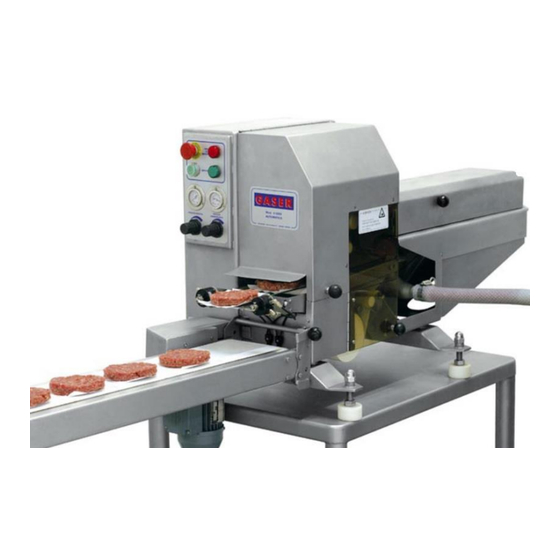
- Page 1 AUTOMATIC HAMBURGER FORMING MACHINE Mod. V3000-CP...
-
Page 2: Table Of Contents
INDEX 1. INDUSTRIAS GASER .................... 4 2. EC DECLARATION OF CONFORMITY ..............5 3. HYGIENE CERTIFICATE ..................6 4. INTRODUCTION ....................7 4.1 Safety ....................... 7 4.2 Hygiene ......................7 5. TECHNICAL SPECIFICATIONS ................8 6. RECEIPT AND START-UP ..................9 6.1 Receipt ...................... - Page 3 10.8 Paper ejector overview ................. 38 10.9 Former overview ..................39 10.10 Electrical installation overview ..............40 10.10.1 Electrical cabinet overview .............. 42 10.11 Pneumatic installation overview ..............43 10.11.1 Quick exhaust overview ..............44 10.12 Stacker overview (optional) ................ 45 10.12.1 Stacker paddle overview ..............
-
Page 4: Industrias Gaser
SIMPLER, MORE EFFECTIVE AND MORE ECONOMICAL TECHNIQUE. In the 1990s, INDUSTRIAS GASER expanded into markets in various countries around the world, and not just in the hamburger sector. We are aware that our work would be of no value without the trust of our existing clients and partners or the interest shown by those who wish to join them. -
Page 5: Ec Declaration Of Conformity
It is forbidden to make any change or modification to the machine without the prior written permission of our technical department. Use of the machine in these conditions could cause accidents, in which case INDUSTRIAS GASER S.L. accepts no liability for the improper use of the machine. Salt, CARLOS GARGANTA SERRAMITJA TECHNICAL DIRECTOR INDUSTRIAS GASER S.L. -
Page 6: Hygiene Certificate
* Plastic material: polyethylene terephthalate (PETP), white, density 1.37 g/cm Manufactured in accordance with DIN 50014. * Stainless steel: AISI 304, manufactured in accordance with European regulations EN-10088, Chemical composition: C≤0.07% Si≤0.75% Mn≤2% Cr=18-19% Ni=8-10% Salt, CARLOS GARGANTA SERRAMITJA TECHNICAL DIRECTOR INDUSTRIAS GASER S.L. -
Page 7: Introduction
Any use other than the specified one will involve risk for the user and for the machine. INDUSTRIAS GASER S.L. accepts no liability either for damage to the machine or personal injury or injury to third parties that this use might cause. -
Page 8: Technical Specifications
5. TECHNICAL SPECIFICATIONS Fits any filler Places white paper or cellophane on one or both sides Uses paper from spools (can be personalised) Can also operate without paper 5. Produces 40 to 60 patties/minute (depending on the speed of the filler, type of mixture and whether it is placing paper) 6. -
Page 9: Receipt And Start-Up
When you receive the machine, you must first check that it is in perfect conditions, without any damage, dents or knocks. If there is any problem, we advise you notify the distributor or INDUSTRIAS GASER S.L. directly. 6.2 Start-up 1. The GASER V-3000 machine operates from three-phase power at 380-220 volts (3 phases + earth). - Page 10 7. Connect the machine’s meat entry tube (Pos. 28, General overview) to the filler forming a 90 º angle whenever possible, so that the controls for each hand can easily be accessed from the same position. 8. The feed tube clamps (Pos. 3, Meat entry overview) must be firmly tightened by hand (tools are not needed).
-
Page 11: Operation
The interior mesh belt (Pos. 15, Interior belt overview) must be kept in tension. If not, it could break. It is tensioned using the roller (Pos. 8, Interior belt overview) closest to the blade. 6.3 Operation The machine has two control panels: a front one and a rear one. They both have different functions. 6.3.1 Front control panel The front control panel comprises the emergency stop button (Pos. -
Page 12: Rear Control Panel
0 and 4 ºC after being prepared and mixed or ones minced with a cutter if using frozen meat. 3. GASER machines leave the factory set up so that any piston filler (hydraulic) or a continuous vacuum filler can be connected to them using the appropriate electrical sockets built in to their right-hand side. - Page 13 5. We cannot guarantee the good operation of GASER machines with spools other than the original ones for our brand. 6. It is important that the fillers feeding GASER machines have a steady and uniform mixture outflow at any speed.
-
Page 14: Cleaning
7. CLEANING You must clean the machine when you have finished production. To do so, follow the steps below. 1. When all of the mixture has been used, stop the filler. Draw back the piston until it draws in all of the mixture that is inside the feed tube Next, disconnect the plastic tube (Pos. - Page 15 4. Remove the paper or cellophane spools and store them in dry place, ideally somewhere airtight. 5. Remove the cover (Pos. 2, Former overview) and the former (Pos. 4, Former overview). Image 11. Loosening nuts. Image 12, Removing cover Image 13, Removing shaper 6.
- Page 16 Image 16, Loosening cylinder shaft Image 17, Removing ejector 7. The machine is now ready for cleaning. We recommend cleaning it with a damp cloth, otherwise the machine’s internal elements could be damaged. 8. Clean the remaining elements separately. Clean the former with water at a temperature not exceeding 40 °C.
-
Page 17: Maintenance
8. MAINTENANCE 1. Periodically check the condition of all moving parts: the mesh belt, traction belts, rollers, gears, bearings, and bushes. 2. Periodically check the condition of the geared motor. 3. Periodically check the general condition of the belt. 4. If any of the rods on the wire mesh belts break, replace the broken rod with a new one using a connecting tube. -
Page 18: Troubleshooting
9. TROUBLESHOOTING The table below lists the problems that might occur with the machine, their potential causes, and how to solve them. Problem Cause Solution See section “6.2 Start-up” Machine unplugged Guard open or not properly closed. The paper or cellophane has run out or the cables The machine does not start Red pilot light lit are in poor condition. - Page 19 If the measurement is bigger than 135 mm, reduce the length of the paper. The blade cuts off part of the patty. The paper does not measure 134 ± 1 mm. If the size is under 133 mm, lubricate the bushings on the ends of the two axles of the mesh belt, the central neck, and the contact roller.
-
Page 20: General Diagram
10. GENERAL DIAGRAM 10.1 General overview Number Description Reference Units MACHINE CHASSIS 30010100 BASE FEET 30130100 LEG STUD 30130200 PLASTIC BLOCK FOR THE FEET 30130300 MECHANISM BOX COVER 30160800-MH FORMER CYLINDER 63/150 PLEASE CONSULT BLADE GUIDE GUARDRAIL FASTNER 00060500 INLET CONNECTION 30020400 FORMER PLATE PLEASE CONSULT... - Page 21 PAPER TENSIONING ROLLER AXLE 30055700 PAPER TENSIONING ROLLER 30055600 PRESSURE ROLLER SPRING 30053000 MAIN UPPER SPOOL SUPPORT 30051500-S UPPER SPOOL SUPPORT 30052400-S LOWER-UPPER SPOOL AXLE 30053800-R PAPER PASSAGE OPENING AXLE 30056000 PAPER PASSAGE OPENING GUIDE BUSHING 30055900 UPPER PAPER GUIDE 30053500 STAINLESS RADIAL BEARING 10-19-7 68002RS SI010968002RS...
- Page 22 CHAIN INNER GUARDRAIL 30041300 BELT BEARING HOUSING 30052100 V3000 GEARBOX WITH AND WITHOUT PAPER SI0525MV0151 V3000 MOTOR EL1420CA050060 STAINLESS BEARING FOR Ø12 SHAFT SI010960012RS STAINLESS CIRCLIP I-28 DIN472 SI0109I280472 80-100 STAINLESS CLIP 9 mm WIDTH SI0126A80100 PAPER EJECTOR OVERVIEW 30260000 OPENING SAFETY MECHANISM 30190500 FORMER UNIT...
- Page 23 Figure 2, General overview 2 Figure 3, General overview 3 -23-...
- Page 24 Figure 4, General overview 4 Figure 5, General overview 5 Figure 6, General overview 6 -24-...
- Page 25 Figure 7, General overview 7 Figure 8, General overview 8 -25-...
-
Page 26: Meat Entry Overview
10.2 Meat entry overview Ref.30110000 Position Description Reference Units INLET TUBE ATTACHMENT BRACKET 30110500 LOWER FEED INLET ELBOW 30110400 ENTRY TUBE CLAMP 00110200 MEAT ENTRY TUBE 00110300 Figure 9, Meat entry overview -26-... -
Page 27: Interior Belt Overview
10.3 Interior belt overview Ref. 30200000 Number Description Reference Units LOWER BELT CHASSIS 30041200 BELT SHAFT BUSHINGS SUPPORT 00040700 INTERIOR BELT BUSHING 30041400 CONVEYOR BELT DRIVE SHAFT 30085100 MESH BELT TOOTHED ROLLER 00040100 LOWER PAPER GUIDE SHAFT 30042400 INNER BELT TENSIONING ROLLER AXLE 30041500 MESH BELT SMOOTH ROLLER 00040300... -
Page 28: Outlet System Bearing Housing Overview
10.3.1 Outlet system bearing housing overview Ref. 33530000 Number Description Reference Units OUTLET SYSTEM BEARING HOUSING 30070600 STAINLESS BEARING FOR Ø8 SHAFT SI010962022RS Figure 11, Outlet system bearing housing overview -28-... -
Page 29: Outlet System Drive Train Overview
10.3.2 Outlet system drive train overview Ref. 33580000-N Position Description Reference Units OUTLET SYSTEM PASSIVE PULLEY 30070500 OUTLET SYSTEM PULLEY DRIVE SHAFT 30072900 OUTLET SYSTEM DRIVEN ROLLER 30072100 OUTLET SYSTEM EXTERNAL DRIVE SHAFT 30072800 Figure 12, Outlet system drive roller overview -29-... -
Page 30: Outlet System Passive Roller Overview
10.3.3 Outlet system passive roller overview Ref. 33590000-N Position Description Reference Units STAINLESS BEARING FOR Ø8 SHAFT SI010962022RS OUTLET SYSTEM PASSIVE ROLLER SHAFT 30073200 OUTLET SYSTEM PASSIVE ROLLER 30072200 Figure 13, Outlet system passive roller overview -30-... -
Page 31: Paper Cutter Overview
10.4 Paper cutter overview Ref. 30060000 Number Description Reference Units 25/50 STAINLESS CYLINDER NE1315025/050I CUTTING CYLINDER SUPPORT 30060500 BLADE COLUMN 30062300 BLADE GUIDE 30060200 V3000 BLADE UNIT 33660000 CUTTING PLATE 30060100 Figure 14, Paper cutter overview -31-... -
Page 32: V3000 Cutting Blade Overview
10.4.1 V3000 Cutting blade overview Ref. 33660000 Number Description Reference Units BLADE SUPPORT 30060700 V3000 BLADE 30060600 PAPER PRESS 30061800 O-RING EPDM 70 SHA Ø7.3 × 2.4 mm SI060907.32.4 PAPER PRESS SPRING SI011407209.23.5 Figure 15, Paper cutter assembly -32-... -
Page 33: Rubber Rollers Overview
10.5 Rubber rollers overview Ref. 30150000 Number Description Reference Units FIXED ROLLERS BEARING HOUSING 30052000 PAPER CARRIER FIXED ROLLER 30053100 BEARING FOR Ø12 SHAFT SI010960012RS BEARING HOUSING INNER TUBE 30052600 PRESSURE ROLLER KNURLED NUT 30053400 CHAIN DRIVE-GEAR 30080100 STAINLESS CIRCLIP I-28 DIN472 SI0109I280472 CYLINDER-GUILLOTINE CONNECTING TUBE 00030800... -
Page 34: Bellows Overview
10.6 Bellows overview Ref. 33690000 Number Description Reference Units BELLOWS BODY 30092100 BELLOWS UPPER COVER 30092200 BELLOWS PISTON 30092300 BELLOWS LOWER COVER 30092400 STAINLESS WASHER M22 DIN125 FE0108M220000125 1 CYLINDER 25/70 NE1315025/070 STAINLESS HEX. NUT THIN M-20 DIN 439 FE0108M200000439 1 STAINLESS HEX NUT M10 DIN934 FE0108M100000934 1 PNEUMATIC COLLAR 125-110-10mm... -
Page 35: Connecting Rod Overview
10.7 Connecting rod overview Ref. 30080000 Number Description Reference Units TOOTHED GEAR WHEEL 00081100 ANTI-ROTATION BEARING UNIT 00520000 TOOTHED GEAR WHEEL AXLE 00081200 COMPLETE CONNECTING ROD OVERVIEW 17960000 TOOTHED WHEEL SUPPORT 30083300 STAINLESS STEEL FORK AND PIN UNIT 00670000 BELT CYLINDER LENGTH REGULATOR 30082400 VESTA CYLINDER 32/80 NE1315032/080... -
Page 36: Complete Connecting Rod Overview
10.7.1 Complete connecting rod overview Ref. 17960000 Number Description Reference Units BUSHING intØ16 extØ18 H25 SI0409018016025 CONNECTING ROD 00081400 BEARING SUPPORT 00081700 Figure 19, Complete connecting rod overview -36-... -
Page 37: Anti-Rotation Bearing Overview
10.7.2 Anti-rotation bearing overview Ref. 00520000 Number Description Reference Units BEARING HOUSING 00081900 ANTI-ROTATION BEARING SI0509HFL2530 Figure 20, Anti-rotation bearing overview -37-... -
Page 38: Paper Ejector Overview
10.8 Paper ejector overview Ref. 30260000 Number Description Reference Units PAPER EJECTOR LOWER BLOCK 30121400 COUTERWEIGHT PAPER EJECTOR LOWER BLOCK 30120700 PAPER END BUSHING 00120100 PAPER END LONG ROD 30121000 PAPER EJECTOR SPACER 30121500 UPPER PAPER END SHAFT 30120100 SHORT PAPER END ROD 30121100 PLASTIC PAPER-END STUD 30121700... -
Page 39: Former Overview
10.9 Former overview Ref. PLEASE CONSULT Position Description Reference Units FORMER COVER KNOB 35000200 FORMER COVER PLEASE CONSULT COVER SIDE PLEASE CONSULT FORMER PLEASE CONSULT Figure 22, Former overview -39-... -
Page 40: Electrical Installation Overview
10.10 Electrical installation overview Ref. 30100000 Number Description Reference Units ELECTRICAL PANEL OVERVIEW 30250000 CONTINUOUS FILLER SUPPORT BASE UNIT 30760000 ELECTRICALLY-CONTROLLED VALVE UNIT 30770000 CONNECTION no. 1 ELECTRICALLY-CONTROLLED VALVE UNIT 30840000 CONNECTION no. 2 ELECTRICALLY-CONTROLLED VALVE UNIT 30850000 CONNECTION no. 3 ELECTRICALLY-CONTROLLED VALVE 30890000 CONNECTOR CABLE UNIT... - Page 41 Figure 24, Electrical installation overview 2 Figure 25, Electrical installation overview 3 -41-...
-
Page 42: Electrical Cabinet Overview
EL0920RMY2IAN24 2 POWER SUPPLY CONNECTION BASE EL0220S3B POWER SUPPLY 24V EL1120FA24V3000 CIRCUIT BREAKER 16A “C” 3P EL0402MGIII16A CIRCUIT BREAKER 4A “C” 1P EL0402MGI04A CIRCUIT BREAKER 2A “C” 1P EL0402MGI02A PANASONIC PLC V3000-CP 33860000 TIMER EL1720TZH3DSS Figure 26, Electrical cabinet overview -42-... -
Page 43: Pneumatic Installation Overview
10.11 Pneumatic installation overview Ref. 30220000 Number Description Reference Units FILTER CONTROL 3/8” 0-8B NE0215FR08B38 MANIFOLD NE0315DJ5214 QUICK EXHAUST UNIT 33560000 ELECTRICALLY-OPERATED VALVE 1/4 NE0315EV5214 ELECTRICALLY-OPERATED VALVE 1/8 NE0315EV5218 DISTRIBUTOR 40 × 40 × 20 1/4” NE0315R40402014 DISTRIBUTOR 50 × 50 × 25 3/8” NE0315R50502538 SELECTOR VALVE 1/8”... -
Page 44: Quick Exhaust Overview
10.11.1 Quick exhaust overview Ref. 33560000 Number Description Reference Units INTERIOR MEMBRANE NE0215MER12 Figure 28 Quick exhaust overview -44-... -
Page 45: Stacker Overview (Optional)
10.12 Stacker overview (optional) Ref. 34000000 Number Description Reference Units STACKER PADDLE UNIT 33550000 CONVEYOR BELT UNIT 00360000 Figure 29, Stacker overview -45-... -
Page 46: Stacker Paddle Overview
10.12.1 Stacker paddle overview Ref. 33550000 Number Description Reference Units RIGHT STACKER CYLINDER SUPPORT 34020100 ROTATING STACKER CYLINDER NE1315BW2090S LEFT STACKER CYLINDER SUPPORT 34020200 STACKER PADDLE LEFT ARM 34020600 STACKER PADDLE RIGHT ARM 34020500 STACKER PADDLE 34020400 Figure 30, Stacker paddle overview -46-... -
Page 47: Conveyor Belt Overview
10.12. Conveyor belt overview Ref. 00360000 Number Description Reference Units CONVEYOR BELT CHASSIS 00350100 CETACT PLUG 3 POLE + EARTH 16A EL0220CC3PT16A BELT MOTOR GUARD 00350300 LEFT BELT SUPPORT 33350400 CONVEYOR BELT SUPPORT PIN 33350500 RIGHT BELT SUPPORT 33350300 MOTOR PLEASE CONSULT CONVEYOR BELT TENSIONING ROLLER 00590000... -
Page 48: Pneumatic Diagrams
12. PNEUMATIC DIAGRAMS Position Description Reference Units FORMER CYLINDER 63/150 PLEASE CONSULT BELT VESTA CYLINDER 32 × 80 NE1315032/080 STAINLESS EJECTOR CYLINDER 25/70 NE1315025/070I STAINLESS BLADE CYLINDER 25/50 NE1315025/050I QUICK EXHAUST 1/2” 33560000 FLOW CONTROL Ø6 1/8” NE0815RC0618 ELECTRICALLY-CONTROLLED VALVE 1/4 NE0315EV5214 ELECTRICALLY-CONTROLLED VALVE 1/8 NE0315EV5218... - Page 49 Diagram 1, Pneumatic diagram -49-...
-
Page 50: Wiring Diagrams
11. WIRING DIAGRAMS 11.1 Hamburger forming machine-Continuous filler connection Diagram 2, Connection between hamburger forming machine and continuous filler -50-... -
Page 51: Plc Inputs And Outputs
1.2 PLC inputs and outputs INPUTS Main Position Description Diagram Ref. CONTACTOR MANUAL PUSH BUTTON PAPER CYLINDER FORMER CYLINDER EXTENDED EJECTOR CYLINDER EXTENDED MIXTURE DETECTOR CYLINDER PAPER CUTTER AND EJECTOR CYLINDERS RETRACTED FORMER CYLINDER RETRACTED STACKER BELT *Positions 1 to 9 refer to the inputs for the magnetic detectors OUTPUTS Main Position... - Page 52 +AR1/1 F26_Gaser Empresa GASER Obra: V3000 - VER 04 AMB PAPER CTRA, BESCANÓ, 15 Calle Referencia: CP/Localidad POL. TORRE MIRONA 17190 CP/Localidad Teléfono +34 972 23 65 72 Teléfono +34 972 23 63 66 E-mail gaser@gaser.com E-mail Nombre de proyecto Lugar de instalación...
- Page 53 +DI1/1 4x2,5 MAQUINA MAQUINA 01T01 CN3 . 8 CN3 . 11 / 2.0 IN 380V OUT 24V CN3 . 10 CN3 . 12 IN 0V OUT 0V / 2.0 MARCHA 100VA 0 - 1 /2.1 24VAC /2.6 24VDC /3.0 /4.2 0155 / 4.0 4x2,5...
- Page 54 / 1.9 / 3.0 CN1 . 2 / 3.0 CN1 . 3 /1.0 CN1 . 6 EMERGENCIA CONTACTOS FINAL PAPEL 03S03 DET.MAGNETICO REARME NC PUERTA 03H01 03H02 CN1 . 4 CN1 . 5 /2.2 / 1.9 / 3.0 /2.6 /2.1 /3.0 /4.2 FINAL DE PAPEL...
- Page 55 / 2.9 / 4.5 / 2.9 / 4.0 /3.0 /3.6 CN3 . 2 CN3 . 3 CN3 . 4 CN3 . 5 CN3 . 6 CN3 . 7 CN1 . 9 CN1 . 10 CN1 . 11 /1.0 /3.8 CN3 . 1 / 2.9 /4.5 FORMADOR...
- Page 56 0155 0155 0155 / 1.9 0166 0166 0166 / 1.9 / 3.9 CN1 . 8 CN2 . 1 0166 PISTON EXPULSAR ARRIBA 1 CAJA FUENTE PISTON ALIMENTACION -02SP01 EXPULSAR ARRIBA 2 /1.0 MANUAL PRESELECTOR BCD COMPLEMENTARIO CORTE 1 5 (22) CORTE 2 CN1 .
- Page 57 LINEA ENTRADA 220/380V HILO Nº PIN CONECTOR HEMBRA CN1 (14cm) HILO Nº PIN CONECTOR HEMBRA CN2 (19cm) HILO Nº PIN CONECTOR HEMBRA CN3 (19cm) HILO Nº PIN Fecha 24/01/2018 0DCI V3000 - VER 04 AMB PAPER Resp. Dep. Electrico CONECTORES Probado Hoja Proyecto nº...
Need help?
Do you have a question about the V3000-CP and is the answer not in the manual?
Questions and answers