Table of Contents
Advertisement
Quick Links
Advertisement
Table of Contents

Related Manuals for GASER T-70


Summary of Contents for GASER T-70
- Page 1 SEMIAUTOMATIC TYING MACHINE Mod. T-70...
-
Page 2: Table Of Contents
INDEX 1. INDUSTRIAS GASER........................3 2. EC DECLARATION OF CONFORMITY....................4 3. HYGIENE CERTIFICATE........................5 4. INTRODUCTION..........................6 4.1 Safety............................6 4.2 Hygiene............................6 5. TECHNICAL SPECIFICATIONS......................7 6. RECEIPT AND START-UP........................8 6.1 Receipt............................8 6.2 Start-up............................8 7. CLEANING............................12 8. -
Page 3: Industrias Gaser
SIMPLER, MORE EFFECTIVE AND MORE ECONOMICAL TECHNIQUE. In the 1990s, INDUSTRIAS GASER expanded into markets in various countries around the world, and not just in the hamburger sector. We are aware that our work would be of no value without the trust of our existing clients and partners or the interest shown by those who wish to join them. -
Page 4: Ec Declaration Of Conformity
It is forbidden to make any change or modification to the machine without the prior written permission of our technical department. Use of the machine in these conditions could cause accidents, in which case INDUSTRIAS GASER S.L. accepts no liability for the improper use of the machine. Salt, CARLOS GARGANTA SERRAMITJA TECHNICAL DIRECTOR INDUSTRIAS GASER S.L. -
Page 5: Hygiene Certificate
* Plastic material: polyethylene terephthalate (PETP), white, density 1.37 g/cm Manufactured in accordance with DIN 50014. * Stainless steel: AISI 304, manufactured in accordance with European regulations EN-10088, Chemical composition: C≤0.07% Si≤0.75% Mn≤2% Cr=18-19% Ni=8-10% Salt, CARLOS GARGANTA SERRAMITJA TECHNICAL DIRECTOR INDUSTRIAS GASER S.L. -
Page 6: Introduction
Any use other than the specified one will involve risk for the user and for the machine. INDUSTRIAS GASER S.L. accepts no liability either for damage to the machine or personal injury or injury to third parties that this use might cause. -
Page 7: Technical Specifications
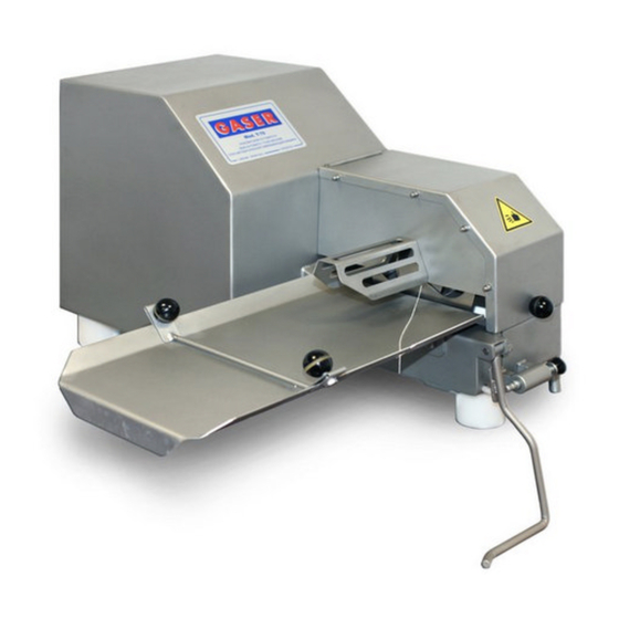
5. TECHNICAL SPECIFICATIONS Type of tying: continuous thread Uses bobbins of thread (mounted on a cone) Pneumatic operation (4-6 kg/cm No electricity supply required. Uses air at normal velocity (80 litres/minute) Knee-operated control with attachment for automatic tying 54 mm inlet Adjustable choking Speed adjustable from 50 to 140 operations/minute Tying with three turns of the thread... -
Page 8: Receipt And Start-Up
When you receive the machine, you must first check that it is in perfect conditions, without any damage, dents or knocks. If there is any problem, we advise you notify the distributor or INDUSTRIAS GASER S.L. directly. 6.2 Start-up 1. It is important that when starting to tie cured meat products, the machine is completely clean to ensure it works properly. - Page 9 Load the thread bobbin on to the articulated shaft (Pos. 2, Tying machine gears with tying tube overview), turning it to the right to tighten and screw it on. Image 2, Loading bobbin on shaft Pass the thread through the hole in the blades Image 3, Passing thread through hole in blades Pass the thread through the brake (Pos.
- Page 10 Do the operation twice by activating the knee-operated control (Pos. 31, overview) without moving the meat forwards so that the thread is fixed. Image 5, Operating knee control 5. On the right of the machine there is an air-flow control. By turning it, you can adjust the air flow and consequently the speed of work.
- Page 11 8. If you want to work continuously, insert the lever fixing shaft (Pos. 32, overview). Image 7, Inserting lever fixing shaft 9. During operation, it is necessary to ensure that the bobbin does not come off its support. -11-...
-
Page 12: Cleaning
7. CLEANING When finishing production, the machine must be cleaned. No parts of the machine need to be dismantled to do this: 1. Lift the upper protection (Pos. 27, overview) using the knob (Pos. 29, overview). Image 8, Opening the lid 2. -
Page 13: Maintenance
8. MAINTENANCE 1. Lubricate the three lubrication points with thin food-grade oil. Two of them are located on the right- hand side of the machine and the other in the twisting mechanism. To be able to lubricate the twisting mechanism, release the air pressure and give the twisting mechanism half a turn until the thread bobbin is at the bottom and the lubrication point at the top. -
Page 14: Troubleshooting
9. TROUBLESHOOTING Problem Cause Solution Machine unplugged See manual “6.2. Start-up”, point 2 The machine does not start Set the flow to its minimum See manual “6.2. Start-up”, point 6 Pneumatic fault See manual “8. Maintenance”, point 4 Insufficient inlet air pressure See manual “6.2. -
Page 15: General Diagram
10. GENERAL DIAGRAM 10.1 Overview Number Description Reference Units T-70 TYING MACHINE CHASSIS 70010100 FEET 70130100 LEG LOWER WASHER 70130200 TYING CORE NUT 00070400 CYLINDER-GEARWHEEL CONNECTION SHAFT 70090300 T-72 METAL GEAR 70090800 T-72 TYING MACHINE INTERMEDIATE GEARS 70090900 T-72 DRIVE CYLINDER SPACER... - Page 16 NOT VALVE NE0215NOTC NOT VALVE BASE 1/8” NE03157097K18 MANIFOLD NE0315DJ5214 E-28310 LIMIT SWITCH NE0315E28310 T-70 DRIVE GEARS LIMIT SWITCH NE0315ER18310 DISTRIBUTOR 40 × 40 × 20 1/4” NE0315R4040201 INTERNAL DISCHARGE VALVE NE0315VDI14 TYING MACHINE SPEED CONTROL NE0815RCW18 NICKEL VALVE VCMS32M08 3/2 1/8”...
- Page 17 Figure 2, General overview 2 Figure 3, General overview 3 -17-...
- Page 18 Figure 4, Pneumatic elements -18-...
-
Page 19: Tying Machine Gears Overview
10.2 Tying machine gears overview Ref. 77620000 Number Description Reference Units TYING MACHINE GEARS 00070100 THREAD BOBBIN SUPPORT CONE 00070500 THREAD TENSIONER INERTIA BRAKE BASE 70071100 THREAD TENSIONER INERTIA BRAKE SUPPORT 70071200 THREAD TENSIONER INERTIA BRAKE 70071300 COUNTERWEIGHT THREAD TENSIONER INERTIA BRAKE SHAFT 70071400 INERTIA STOP STUD 70071600... -
Page 20: Tying Machine Gears With Tying Tube
10.3 Tying machine gears with tying tube Ref. 77530000 Number Description Reference Units TYING MACHINE GEARS OVERVIEW 77620000 TYING CORE 00070200 TYING TUBE 00070300 TYING LUBRICATION POINT SI0122EHCM8 PLAIN BEARING SI0409070065050 Figure 6, Tying machine gears with tying tube -20-... -
Page 21: Tensioner With Thread Guide Overview
10.4 Tensioner with thread guide overview Ref. 77610000 Number Description Reference Units THREAD TENSIONER SUPPORT 00070600 THREAD TENSIONER 00070700 T-72 TYING MACHINE THREAD TENSIONING SI011418102096 SPRING Figure 7, Tensioner with thread guide overview -21-... -
Page 22: Drive Gear Overview
10.5 Drive gear overview Ref. 77630000-N Position Description Reference Units TYING MACHINE DRIVE GEARS 00090100 DRIVE GEAR CAM 00091200 T-72 METAL DRIVE GEAR SPACER 70090200 Figure 8. Drive gear overview -22-... -
Page 23: Drive Shaft Overview
10.6 Drive shaft overview Ref. 77800000 Number Description Reference Units T-72 DRIVE GEAR SHAFT 70090500 T-72 DRIVE GEAR SHAFT WASHER 70090700 T-72 LARGE INTERIOR RING REINFORCEMENT 70091400 T-72 LARGE INNER RING 70091500 TYING LUBRICATION POINT SI0122EHCM8 Figure 9, Drive shaft overview -23-... -
Page 24: Intermediate Shaft Overview
10.7 Intermediate shaft overview Ref. 77600000 Number Description Reference Units INTERMEDIATE GEARS SHAFT 70091700 T-72 SMALL INNER RING 70091600 T-72 SMALL RING REINFORCEMENT 70091800 TEFLON WASHER 70091900 TYING LUBRICATION POINT SI0122EHCM8 Figure 10. Intermediate shaft overview -24-... -
Page 25: Filter Regulator With Pressure Gauge Unit
10.8. Filter regulator with pressure gauge unit Ref. 77550000 Number Description Reference Units FILTER REGULATOR 1/4” NE0215FR08B14 PRESSURE GAUGE NE0215M12B40 Figure 11. Filter regulator with pressure gauge unit -25-... -
Page 26: Pneumatic Diagram
NOT VALVE NE0215NOTC NOT VALVE BASE 1/8” NE03157097K18 MANIFOLD NE0315DJ5214 E-28310 LIMIT SWITCH NE0315E28310 T-70 DRIVE GEARS LIMIT SWITCH NE0315ER18310 DISTRIBUTOR 40 × 40 × 20 1/4” NE0315R4040201 INTERNAL DISCHARGE VALVE NE0315VDI14 TYING MACHINE SPEED CONTROL NE0815RCW18 NICKEL VALVE VCMS32M08 3/2 1/8”... - Page 27 Pneumatic diagram 1 -27-...
- Page 28 -28-...
Need help?
Do you have a question about the T-70 and is the answer not in the manual?
Questions and answers