Table of Contents
Advertisement
Quick Links
Advertisement
Table of Contents

Related Manuals for GASER MINI


Summary of Contents for GASER MINI
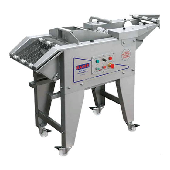
- Page 1 AUTOMATIC BATTER-BREADING MACHINE Mod. MINI...
-
Page 2: Table Of Contents
INDEX 1. INDUSTRIAS GASER .................... 4 2. EC DECLARATION OF CONFORMITY ..............5 3. HYGIENE CERTIFICATE ..................6 4. INTRODUCTION ....................7 4.1 Safety ....................... 7 4.2 Hygiene ......................7 5. TECHNICAL SPECIFICATIONS ................8 6. RECEIPT AND START-UP ..................9 6.1 Receipt ...................... - Page 3 10.8 Overview complete batter belt tensioning shaft ..........31 10.9 Overview complete batter belt lower shaft ............ 32 10.10 Overview complete batter belt lowering unit ..........33 10.11. Complete MINI breader overview .............. 34 10.12 Gear motor overview .................. 35 10.13 Control panel overview ................36 10.14 Electrical cabinet overview .................
-
Page 4: Industrias Gaser
SIMPLER, MORE EFFECTIVE AND MORE ECONOMICAL TECHNIQUE. In the 1990s, INDUSTRIAS GASER expanded into markets in various countries around the world, and not just in the hamburger sector. We are aware that our work would be of no value without the trust of our existing clients and partners or the interest shown by those who wish to join them. -
Page 5: Ec Declaration Of Conformity
It is forbidden to make any change or modification to the machine without the prior written permission of our technical department. Use of the machine in these conditions could cause accidents, in which case INDUSTRIAS GASER S.L. accepts no liability for the improper use of the machine. Salt, CARLOS GARGANTA SERRAMITJA TECHNICAL DIRECTOR INDUSTRIAS GASER S.L. -
Page 6: Hygiene Certificate
* Stainless steel: AISI 304, manufactured in accordance with European regulations EN-10088, Chemical composition: C≤0.07% Si≤0.75% Mn≤2% Cr=18-19% Ni=8-10% AISI 316, manufactured in accordance with European regulations EN-10088, Chemical composition: C≤0.03% Si≤1% Mn≤2% Cr=18.5-16.5% Ni=13-10% Mo=2.5-2% Salt, CARLOS GARGANTA SERRAMITJA TECHNICAL DIRECTOR INDUSTRIAS GASER S.L. -
Page 7: Introduction
Any use other than the specified one will involve risk for the user and for the machine. INDUSTRIAS GASER S.L. accepts no liability either for damage to the machine or personal injury or injury to third parties that this use might cause. -
Page 8: Technical Specifications
5. TECHNICAL SPECIFICATIONS Automatic battering and breading Can be fully dismantled for ease of cleaning Easy maintenance Made from stainless steel and plastics suitable for use with food Mounted on 4 legs with stainless steel wheels Tray support at outlet Blower to remove excess batter Reversible direction for emptying bread Variable belt speed from 9 to 15 metres/minute... -
Page 9: Receipt And Start-Up
When you receive the machine, you must first check that it is in perfect conditions, without any damage, dents or knocks. If there is any problem, we advise you notify the distributor or INDUSTRIAS GASER S.L. directly. 6.2 Assembly The MINI model batter-breading machines are supplied disassembled. These machines essentially comprise 9 parts (Image 1). - Page 10 The process for assembling the machine is described below. 1. Fit each of the legs (Pos. 1, Image 1) using the 3 screws and the 3 M10 cap nuts. The legs include the guides for the tray supports. 2. Once the legs have been attached, attach the two crossbars (Pos. 2, Image 1) using the screws and M8 nuts.
-
Page 11: Start-Up
1. It is important that when the machine starts working, it is completely clean to ensure it operates properly. 2. The MINI model breading machine works on single phase 220 V 50 Hz electrical current. 3. To start breading, first turn the machine on using the ON/OFF position selector knob (Pos. 54, Overview). -
Page 12: Notes
6.4 Notes 1. The wire mesh battering and breading belts must operate under tension. You should also remember that they loosen in use. There is a shaft for tensioning them (Pos. 11 and 12, Overview). To use this, slide both ends in the appropriate direction by the same amount. Working with the wire mesh belts loose or too tense can cause damage. -
Page 13: Cleaning
7. CLEANING When you have finished using the machine, it must be cleaned. To do so, follow these steps: 1. Remove the air blower outlet mouth (Pos. 45, Overview) and the blower outlet elbow (Pos. 44, Overview). Image 6. Mouth removal Image 7. - Page 14 Image 11. Batter belt removal Image 12. Removing batter tank 4. Remove the breader (Pos. 15, Overview). Image 13. Breader removal 5. To empty the bread, use the direction reverser (Pos. 55, Overview) and empty it through the discharge door (Pos. 26, Overview). First, run the belt in forward direction to remove accumulated bread.
- Page 15 6. Remove the breading belt (Pos. 29, Overview) by removing the two knobs (Pos. 34, Overview). Image 16. Removing knobs Image 17. Breading belt removal 7. Clean the disassembled components with pressurised water and dry well, if possible with air. Clean the machine’s chassis with a damp cloth.
-
Page 16: Maintenance
8. MAINTENANCE Periodically check the condition of all moving parts: belt, rollers, gears and bearings. Periodically check the condition of the gear motor. Periodically check the general condition of the machine. If any of the rods on the wire mesh belts break, replace the broken rod with a new one using a connecting tube. -
Page 17: Troubleshooting
9. TROUBLESHOOTING The table below lists the problems that might occur with the machine, their potential causes and how to solve them. Problem Cause Solution See manual “6.2. Start-up”, point Machine unplugged The batter tank is not correctly Locate it using its own centring The machine does not start positioned pieces. -
Page 18: General Diagram
BELT UNIT LOWER SHAFT COMPLETE BATTER BELT 44790000 UNIT COMPLETE SHAFT BATTER BELT 44780000 LOWERING ASSEMBLY UNIT COMPLETE MINI BREADER 44820000 UNIT CONTROL PANEL 40250000 UNIT ELECTRICAL CABINET 40260000 UNIT GEAR MOTOR PLEASE CONSULT BLANK CONTROL PANEL COVER 40160800 PANEL INSIDE PROTECTOR... - Page 19 LS-11 LIMIT SWITCH EL0220LS11 COVER CONNECTOR GLAND EL0220PMA20G SINGLE PHASE PLUG 1409-19 EL0220CEM GENERAL SWITCH EL1320IL20A REVERSE KNOB 44970000 BREADER ON-OFF STICKER PA023040OFON D-120 ROUND BREADER STICKER PA0230D120 TRIANGULAR FRONT MINI STICKER PA0230FT40 BREADER REAR COVER STICKER PA0230TP40 CE MARKING PA0230CE -19-...
- Page 20 Figure 1. Standard overview 1 Figure 2. Standard overview 2 -20-...
- Page 21 Figure 3. Standard overview 3 Figure 4. Standard overview 4 -21-...
- Page 22 Figure 5. Standard overview 5 -22-...
-
Page 23: Overview Complete Breading Belt Drive Shaft
10.2 Overview complete breading belt drive shaft Ref. 44670000 Number Description Reference Units BREADING BELT DRIVE GEAR UNIT 44580000 BREADING BELT DRIVE SHAFT 40030400 BREADING BELT TOOTH ROLLER 40000100 DRIVE SHAFT SPACING ROLLER 40031400 GEAR END WASHER 40000500 E-15 DIN 471 STAINLESS CIRCLIP SI0109E150471 VITON FPM 70 SHA Ø13 ×... -
Page 24: Overview Complete Breading Belt Drive Gears
10.2.1 Overview complete breading belt drive gears Ref. 44580000 Number Description Reference Units BREADING BELT DRIVE GEARS 40031000 DRIVE GEAR SPACER 40001100 STAINLESS SCREW M6x30 DIN963 FE0108M060300963 3 HEX NUT M6 DIN934 FE0108M060000934 3 Figure 9. Overview complete breading belt drive gears -24-... -
Page 25: Overview Batter Belt Drive Shaft
10.3 Overview batter belt drive shaft Ref. 44680000 Number Description Reference Units BATTER BELT DRIVE GEAR UNIT 44590000 BATTER BELT DRIVE SHAFT 40040400 BREADING BELT TOOTH ROLLER 40000100 CRANK REAR SPACER 40041300 BATTER BELT CRANK 40041400 GEAR END WASHER 40000500 E-15 DIN 471 STAINLESS CIRCLIP SI0109E150471 VITON FPM 70 SHA Ø13 ×... -
Page 26: Overview Batter Belt Drive Gears
10.3.1 Overview batter belt drive gears Ref. 44590000 Number Description Reference Units BATTER BELT DRIVE GEARS 40041000 DRIVE GEAR SPACER 40001100 STAINLESS SCREW M6x30 DIN963 FE0108M060300963 3 HEX NUT M6 DIN934 FE0108M060000934 3 Figure 11. Overview batter belt drive gears -26-... -
Page 27: Overview Complete Breading Belt Bearing Housing
10.4 Overview complete breading belt left/right bearing housing Overview complete left bearing housing, Ref. 44620000 Overview complete right bearing housing, Ref. 44630000 Position Description Reference Units BREADING BELT RIGHT BEARING HOUSING 40030700 BREADING BELT LEFT BEARING HOUSING 40030800 BEARING SI010962022RS RETAINING SEAL SI0109I350472 STAINLESS CIRCLIP... -
Page 28: Overview Complete Batter Belt Bearing Housing
10.5 Overview complete batter belt bearing housing Ref. 44640000 Number Description Reference Units BATTER BELT BEARING HOUSING 40040700 BEARING SI010962022RS RETAINING SEAL SI0109I350472 STAINLESS CIRCLIP SI0209R351607 Figure 13. Complete batter belt bearing housing -28-... -
Page 29: Overview Complete Breading Belt Passive Rollers
10.6 Overview complete breading belt passive rollers Ref. 44760000 Number Description Reference Units BREADING BELT PASSIVE ROLLER AXLE 40030500 BREADING BELT SMOOTH ROLLER 40000300 VITON FPM 70 SHA Ø13 × 2.5mm O-RING SI06090132.5 Figure 14. Overview complete breading belt passive roller axle -29-... -
Page 30: Overview Complete Breading Belt Tensioning Shaft
10.7 Overview complete breading belt tensioning shaft Ref. 44560000 Number Description Reference Units BREADING BELT PASSIVE ROLLER AXLE 40030500 BREADING BELT TENSIONING ROLLER 40031500 O-RING VITON FPM 70 SHA Ø13 × 2.5mm SI06090132.5 Figure 15. Overview complete breading belt tensioning shaft -30-... -
Page 31: Overview Complete Batter Belt Tensioning Shaft
10.8 Overview complete batter belt tensioning shaft Ref. 44770000 Number Description Reference Units BATTER BELT PASSIVE ROLLER AXLE 40040500 BATTER BELT TENSIONING ROLLER C3000300 VITON FPM 70 SHA Ø13 × 2.5mm O-RING SI06090132.5 Figure 16. Overview complete batter belt tensioning shaft -31-... -
Page 32: Overview Complete Batter Belt Lower Shaft
10.9 Overview complete batter belt lower shaft Ref. 44790000 Number Description Reference Units BATTER BELT LOWER SHAFT 40040800 BATTER BELT LOWER ROLLER 40040900 VITON FPM 70 SHA Ø6x2.5mm O-RING SI06090062.5 Figure 17. Overview complete batter belt lower shaft -32-... -
Page 33: Overview Complete Batter Belt Lowering Unit
10.10 Overview complete batter belt lowering unit Ref. 44780000 Number Description Reference Units BATTER BELT LOWERING SECTION ROLLER 40041700 AXLE CRANK FRONT SPACER 40041200 BATTER BELT LOWERING SECTION ROLLER 40041800 VITON FPM 70 SHA Ø6x2.5mm O-RING SI06090062.5 Figure 18. Overview complete batter belt lowering unit shaft -33-... -
Page 34: Complete Mini Breader Overview
10.11. Complete MINI breader overview Ref. 44820000 Number Description Reference Units MINI BREADER 40180100 OUTLET CURTAIN SUPPORT ROD 40180200 OUTLET CURTAIN VANES 40180300 Figure 19. Complete COMPACT breader overview -34-... -
Page 35: Gear Motor Overview
10.12 Gear motor overview Ref. PLEASE CONSULT Position Description Reference Units BREADER MOTOR PLEASE CONSULT MINI GEARBOX SI0525BR03020090 1 Figure 20. Gear motor overview -35-... -
Page 36: Control Panel Overview
10.13 Control panel overview Ref. 40250000 Number Description Reference Units CONTROL PANEL PA0230COM40 RED LED D-22 24V EL2120PRD2224V GREEN LED D-22 24V EL2120PVD2224V EMERGENCY STOP 44930000 RED PUSH BUTTON Ø22 44920000 GREEN PUSH BUTTON Ø22 44910000 POTENTIOMETER EL102010KM22 POTENTIOMETER PROTECTOR EL1020PPD22 Figure 21. -
Page 37: Electrical Cabinet Overview
Reference Units ELECTRICAL CABINET EL0220UCP320 PM-20 PUSH-FIT GLAND EL0208RPM20 PM-20 GLAND NUT EL0208TPM20 EARTH TERMINAL EL0220BWPE04 MINI-CONTACTOR EL0220MCGMC6 CIRCUIT BREAKER 6A “C” I+N EL0402MG6ACIN CIRCUIT BREAKER 2A “C” 1P EL0402MGI02A FREQUENCY TRANSVERTOR PLEASE CONSULT 40W TRANSFORMER EL1420TP401S COMPLETE 8 POLE FEMALE CONNECTOR... - Page 38 Figure 22. Electrical cabinet overview 1 Figure 23. Electrical cabinet overview 2 -38-...
-
Page 39: Wiring Diagrams
12. WIRING DIAGRAMS -39-... - Page 40 +AR1/2 F26_Gaser Empresa GASER Obra: MINI VER 01 CTRA, BESCANÓ, 15 Calle Referencia: CP/Localidad POL. TORRE MIRONA 17190 CP/Localidad Teléfono +34 972 23 65 72 Teléfono +34 972 23 63 66 E-mail gaser@gaser.com E-mail Nombre de proyecto Lugar de instalación Descripción de proyecto...
- Page 41 Wiland 5P Forw/Rev. 4x1,5 mm² Chasis -CN3 Máquina /3.7 Turbina encolante Motor Cinta 0.7A 1.59A/0.91A 0.09Kw 0.25Kw 2800rpm 1350rpm Reductor 1:20 Fecha 05/02/2018 0DCI MINI VER 01 Resp. Dep. Electrico POTENCIA Probado Hoja Proyecto nº : Cambio Fecha Nombre Original...
- Page 42 /3.7 /3.6 Botonera /4.6 Verde Marcha / 4.2 -CN3 -CN4 3 /2.4 /3.7 /2.6 4 /2.4 /3.9 /3.3 /2.0 /3.8 /3.5 Fecha 05/02/2018 0DCI MINI VER 01 Resp. Dep. Electrico MANIOBRA Probado Hoja Proyecto nº : Cambio Fecha Nombre Original...
- Page 43 Marcha 0.75 /3.2 Emerg. CHASIS MAQUINA - BOTONERA CN2 -> 8 pins (dins del quadre) CN3 -> 12 pins (dins del quadre) Fecha 22/01/2018 0DCI MINI VER 01 Resp. Dep. Electrico BOTONERA Probado Hoja Proyecto nº : Cambio Fecha Nombre...
Need help?
Do you have a question about the MINI and is the answer not in the manual?
Questions and answers