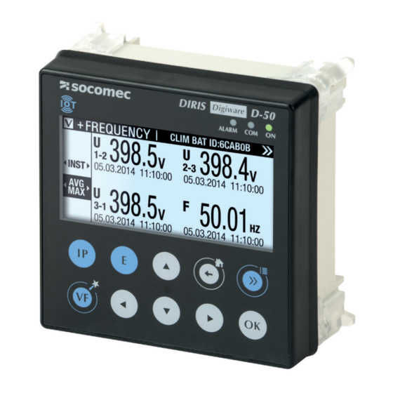
socomec DIRIS Digiware D-50 Installation And Operating Manual
Display and power supply interface
Hide thumbs
Also See for DIRIS Digiware D-50:
- Instruction manual (70 pages) ,
- Manual (2 pages) ,
- User manual (56 pages)

Related Manuals for socomec DIRIS Digiware D-50


Summary of Contents for socomec DIRIS Digiware D-50
- Page 1 INSTALLATION AND OPERATING MANUAL DIRIS Digiware D-50 & D-70 Display and power supply interface...
-
Page 2: Table Of Contents
9.2. Ethernet connection mode ............DIRIS Digiware D-50 & D-70 - 548088B - SOCOMEC... - Page 3 Annex I - 4. SNMP ports ............. .56 Annex I - 5. Retrieving data using the DIRIS Digiware D-50 / D-70 MIB file ......56 Annex I - 6.
-
Page 4: Documentation
1. DOCUMENTATION All documentation on DIRIS Digiware D-50 and D-70 is available on the SOCOMEC website: www.socomec.com/en/diris-d DIRIS Digiware D-50 & D-70 - 548088B - SOCOMEC... -
Page 5: Hazards And Warnings
• The auxiliary power supply voltage indicated on the product is observed: 24 VDC ± 15%. • Use 230 VAC / 24 VDC SOCOMEC power supply (P15 15W 4829 0120) or use a 1 A 24 VDC safety fuse. Failure to respect these precautions could cause damage to the device. -
Page 6: Preliminary Operations
• The packaging includes the device fitted with removable terminal blocks and a Quick start guide. 4. CYBER SECURITY RECOMMENDATIONS & BEST PRACTICES* The DIRIS Digiware D-50/D-70, as any device connected to a user’s Ethernet network, must be protected against any risk of cyber-attack or data loss/destruction. - Page 7 (external hard drive, USB flash drive, wireless communication provision etc.). Finally, in terms of a server like the DIRIS Digiware D-50/D-70, it should be protected by controlling and limiting physical access to the rooms and cabinets hosting the device.
-
Page 8: Introduction
Centralised products can be shown as well as configured by DIRIS Digiware D displays. 5.2.1. Introduction to DIRIS Digiware D-50 The DIRIS Digiware D-50 display is a master on the Digiware bus and acts as a gateway interface to communicate measurements over RS485 and Ethernet. -
Page 9: Introduction To Diris Digiware
Specific configuration Load curves are then The logs are then recorded automatically). automatically downloaded automatically downloaded from the meter’s cache from the meter’s cache memory to the D-70. memory to the D-70. DIRIS Digiware D-50 & D-70 - 548088B - SOCOMEC... -
Page 10: Touchscreens
Use this to go back to a previous navigation menu Use this to go to the previous/next product (to scroll through all your meters and centralised measuring devices) Use this to confirm your navigation or entry selection DIRIS Digiware D-50 & D-70 - 548088B - SOCOMEC... -
Page 11: Led Display
- Stable: device is powered 5.5. Navigation LOADS MEASUREMENTS VOLTAGES LOAD PHASE-NEUTRAL INPUTS/OUTPUTS CURRENTS PHASE-PHASE LOAD PROTECTION NET. FREQUENCY POWERS EVENTS . . . PARAMETERS ..Press for 3 sec. DIRIS Digiware D-50 & D-70 - 548088B - SOCOMEC... -
Page 12: Menu Structure
EMAIL Last activity FTP CLIENT Last activity Consumptions DATALOGGER Trends Alarms IP ADDRESS MAC ADDRESS SERIAL NUMBER ABOUT SOFTWARE VERSION REBOOT Note: the menus available depend on the slave device connected. DIRIS Digiware D-50 & D-70 - 548088B - SOCOMEC... -
Page 13: Dimensions
5.7. Dimensions Dimensions in/mm Door cut-out must be 92x92mm. DIRIS Digiware D-50 & D-70 - 548088B - SOCOMEC... -
Page 14: Mounting
6.1. Recommendations and safety Refer to the safety instructions (section “2. Hazards and warnings”, page 5) 6.2. Door mounting DIRIS Digiware D-50 and D-70 are panel-mounted (cut-out: 92x92mm). The display is secured with clips. DIRIS Digiware D-50 & D-70 - 548088B - SOCOMEC... -
Page 15: Din Rail Mounting
6.3. DIN rail mounting DIRIS Digiware D-50 and D-70 can also be mounted on a DIN rail using a dedicated accessory (4829 0230) sold separately. DIN rail mouting kit (separate part number: 4829 0230) STEP 1 1Nm max STEP 2... -
Page 16: Communication Architectures
(20 W max) 120 Ω (*) The use of a 1A / 24 VDC fuse protection is recommended if the 24 VDC power supply is not provided by Socomec. For North America, the use of recognized fuses is mandatory. All inputs/outputs are considered as SELV (Safety Extra-Low Voltage). -
Page 17: Configuration
8. CONFIGURATION From the Socomec start-up sreen, press “OK” to enter the navigation menu: ID: E5C801 Select the "PARAMETERS" menu by using the navigation key "DOWN ARROW" 3x and confirm with "OK”: HOME LOADS MEASURES INPUTS/OUTPUTS PROTECTION EVENTS PARAMETERS Enter the password "100" using the arrow pad (4 arrow keys) and confirm with "OK":... -
Page 18: Display-Specific Settings
• ETHERNET COMMUNICATION: to set the display's IP address • SET REMOTE DEVICE DATE/TIME: to set the date and time • CHANGE PASSWORD: to change the password to access the settings menu (default: "100") DIRIS Digiware D-50 & D-70 - 548088B - SOCOMEC... -
Page 19: Language
Configure the baudrate, stop bits, parity of the RS485 and Digiware bus. DIRIS Digiware D-50 / D-70 are master devices on Digiware and RS485 buses (baudrate, parity, stop bits). PARAMETERS BAUDRATE: 38400 STOP: 1BIT PARITY: NONE ADDRESS: DIRIS Digiware D-50 & D-70 - 548088B - SOCOMEC... -
Page 20: Ethernet Communication
• Manually by entering the year, month, day, hour, minute, second • Automatically (like a computer) by SNTP server If the DIRIS Digiware D-50/D-70 is synchronised by SNTP, it will broadcast and synchronise the date and time of all downstream devices. -
Page 21: Automatic Detection Of Slave Devices
CONFIGURE A DEVICE AUTODETECT SERIAL DEVICES LIST PRODUCTS ADD NEW DEVICE … Click on “DIGIWARE ADDRESSING RANGE”: AUTODETECT STATUS STOPPED FOUND / CONFLICT 000 / 000 DIGIWARE ADDRESSING RANGE 001:247 METHOD FAST START DIRIS Digiware D-50 & D-70 - 548088B - SOCOMEC... - Page 22 - FAST (default mode): this mode will only detect DIRIS Digiware modules on the Digiware bus and RS485 bus, DIRIS B and DIRIS A-40 on the RS485 bus. - FULL: this mode will also detect other Socomec PMDs (DIRIS A) and meters (COUNTIS E) connected on the RS485 bus.
- Page 23 If you have chosen an automatic address conflict resolution ("AUTOSET"), the STATUS automatically goes to "STOPPED" once the auto-discovery process is finished. AUTODETECT STATUS STOPPED FOUND / CONFLICT 002 / 000 DIGIWARE ADDRESSING RANGE 001:247 METHOD FAST START DIRIS Digiware D-50 & D-70 - 548088B - SOCOMEC...
- Page 24 004 / 000 DIGIWARE ADDRESSING RANGE 001:247 METHOD FAST START The number of detected products increases and the number of conflicts decreases to reach zero once all products have a unique address. DIRIS Digiware D-50 & D-70 - 548088B - SOCOMEC...
- Page 25 LOAD1 PARAMETERS DISPLAY CONFIGURE A DEVICE AUTODETECT SERIAL DEVICES LIST PRODUCTS ADD NEW DEVICE … Example: LOAD1 LIST PROD. U-30@3 ID:545434 @003 I-30@4 ID:F0C1D2 @004 I-30@5 ID:F0C1D3 @005 I-30@6 ID:F0C1D4 @006 DIRIS Digiware D-50 & D-70 - 548088B - SOCOMEC...
-
Page 26: Configuring The Diris Digiware System From The D-50/D-70 Display
• Network: setting the type of voltage network: single-phase (1P+N), two-phase (2P), three-phase without neutral (3P), three-phase with neutral (3P+N). • Load: configuring the loads/circuits measured. You can, for example, measure three-phase and single-phase loads connected to a three-phase electrical network. DIRIS Digiware D-50 & D-70 - 548088B - SOCOMEC... - Page 27 Load settings are configured from DIRIS Digiware I-xx modules SELECT PROD.. I-30@4 ID:FOC1D2 @004 U-30@6 ID:546434 @006 I-30@4 ID:FOC1D2 SELECT PROD. LOADS With DIRIS B power monitoring devices, network and loads settings are accessible from the DIRIS B altogether. DIRIS Digiware D-50 & D-70 - 548088B - SOCOMEC...
-
Page 28: Network Configuration
The current sensor connected to the current 2 input measures the current of phase 2 (V2) The current sensor connected to the current 3 input measures the current of phase 1 (V1) DIRIS Digiware D-50 & D-70 - 548088B - SOCOMEC... - Page 29 (+/DIRECT = P1 --> P2) or backwards (-/INV = P2 --> P1) I-30@4 ID:FOC1D2 LOAD INPUT 250 A 250 A 250 A +/DIRECT +/DIRECT +/DIRECT LINE V LOAD TYPE 3P+N_3CT 3P+N_3CT 3P+N_3CT PRESS OK TO ENTER SETTINGS DIRIS Digiware D-50 & D-70 - 548088B - SOCOMEC...
- Page 30 • CT -> Indicates the rating of the current sensor used. Click on “DETECT” to automatically detect the rating. After 2 seconds, the rating is displayed. Complete the process by selecting "OK" then "OK" again DIRIS Digiware D-50 & D-70 - 548088B - SOCOMEC...
- Page 31 When all the circuits/loads are configured (maximum 3 on one DIRIS Digiware I-30), apply your settings by selecting "SEND SETTINGS" and click "OK". I-30@4 ID:FOC1D2 LOAD … CT SETTINGS CT SETTINGS SEND SETTINGS DIRIS Digiware D-50 & D-70 - 548088B - SOCOMEC...
-
Page 32: Configuration Via Easy Config System
The Easy Config System software can be downloaded from the Socomec website at the following link: www.socomec.com/easy-config-system_en.html The Configuration of the DIRIS Digiware D-50/D-70 display and downstream Socomec devices can be done from the Easy Config System software, by connecting a computer to the D-50/D-70 display either via USB or via Ethernet. -
Page 33: Ethernet Connection Mode
- Click on the “Binocular” icon on the left side bar. - In the “Organisation” part, select the D-70/D-50 display. - In the “Data” part, click on “Dashboard” to visualise general information about the display. - Click on “Auto-discovery” (1). DIRIS Digiware D-50 & D-70 - 548088B - SOCOMEC... - Page 34 “Organisation” part, next to the D-50/D-70 display. - Configuration of slave devices can be done directly by clicking on the Wrench icon on the left side bar and selecting the right device: DIRIS Digiware D-50 & D-70 - 548088B - SOCOMEC...
-
Page 35: Webserver Embedded In The D-50/D-70 Displays
(WEBVIEW-M, D-70 only). To connect to the gateway’s webserver, enter its IP address in the address bar of your web browser. Default Ethernet parameters of the DIRIS Digiware D-50/D-70 displays are as follows: - IP address: 192.168.0.4 - Mask: 255.255.255.0... - Page 36 1 hour. If you do not wish to wait 1 hour, you can reboot the D-50/D-70 display. If you have forgotten to save the passphrase, the only option left is to reset the D-50/D-70 to factory default settings DIRIS Digiware D-50 & D-70 - 548088B - SOCOMEC...
-
Page 37: Admin Profile
10.2. Admin profile When connected as Admin, you can access the configuration page by clicking on the “wrench/screwdriver” icon on the top left corner: 10.2.1. “Devices” tab • Go to the “Devices” tab: DIRIS Digiware D-50 & D-70 - 548088B - SOCOMEC... - Page 38 • Click on “Modify active configuration” (1), and then click on “Sources” (2): • Click on the “AutoDetect” icon on the right bottom corner to detect and add SOCOMEC devices already present in the D-50/D-70 display’s topology. • Click on the “+” icon at the right bottom corner for manually adding products one at a time. Adding an M-50/M-70 gateway or D-50/D-70 display will add the entire topology under that gateway or display.
- Page 39 U-31 dc ECI32 U-32 dc ECI3 Note: other tabs such as “Hierarchy” and “Photoview” can be configured as well. They offer additional modes for the visualisation and analysis of measurements and consumption. DIRIS Digiware D-50 & D-70 - 548088B - SOCOMEC...
-
Page 40: Protocols" Tab
Management System, etc.) can be configured from the “Protocols” tab. • Network Configuration This tab allows you to modify the gateway’s IP configuration: After modifying those parameters, a reboot of the D-50/D-70 display is necessary. DIRIS Digiware D-50 & D-70 - 548088B - SOCOMEC... - Page 41 ƒ File format: data can be exported in different file formats (CSV and EMS – see appendices 1 and 2). The CSV format is easier to use while EMS is better for importing data into an external energy management software. ƒ Test connectivity: Test the FTP export function DIRIS Digiware D-50 & D-70 - 548088B - SOCOMEC...
- Page 42 Refer to ANNEX. A and B for more information on BACnet and SNMP communication protocols with the D-50/D-70 display. - Time: allows you to configure an SNTP server to automatically synchronise the clock of the D-50/D-70 display to an external computer. DIRIS Digiware D-50 & D-70 - 548088B - SOCOMEC...
- Page 43 ƒ Maximum waiting time: Time to wait to receive the email notification after the alarm is triggered on a device. This allows to limit the number of emails sent by the D-50/D-70 display, especially when the alarm repeatedly changes state. DIRIS Digiware D-50 & D-70 - 548088B - SOCOMEC...
-
Page 44: Cyber Security Profile
- Secure the client-server communication (HTTPS, FTPS, SMTPS). - Prevent denial-of-service attacks by implementing a firewall in the D-50/D-70 display. The configuration of Cyber security functions is explained in paragraphs 10.3.1 through 10.3.4. DIRIS Digiware D-50 & D-70 - 548088B - SOCOMEC... -
Page 45: Security Policy" Tab
10.3.2. “Security Policy” tab DIRIS Digiware D-50/D-70 displays can reduce the attack exposure by disabling certain peripherals or services that are not essential to the customer’s use case. Peripherals - USB: disable the USB port of the D-50/D-70 display. - Bluetooth Low Energy: disable the Bluetooth Low Energy of the D-50/D-70 display. -
Page 46: Https" Tab
This tab allows you to secure the client (D-50/D-70) to server (FTPS, SMTPS) communication by adding the relevant Certificate Authorities (CA) on the Client side. Several common Certificate Authorities are already included to the D-50/D-70 display, but the user can add others if necessary. DIRIS Digiware D-50 & D-70 - 548088B - SOCOMEC... -
Page 47: Firewall" Tab
This tab allows you to implement a firewall to protect against Denial-Of-Service attacks also called Flooding attacks by entering a max bandwidth in kbit/s and a max number of requests per second: A client exceeding one of the above parameters while communicating to the DIRIS Digiware D-50/D-70 display will be blocked for 30 seconds. - Page 48 Upload the desired firmware package (.dfu file) by clicking on the “Browse” button. Wait until the package is loaded, and once package consistency check I finished, click on “Upgrade”: Once the upgrade is finished, the web page will reload automatically: DIRIS Digiware D-50 & D-70 - 548088B - SOCOMEC...
-
Page 49: Webview-M
10.4. WEBVIEW-M For more information on the visualisation of measurement data, please refer to the WEBVIEW-M instruction manual, available on the Socomec website at the following link: https://www.socomec.com/range-software-solutions_en.html?product=/webview_en.html DIRIS Digiware D-50 & D-70 - 548088B - SOCOMEC... -
Page 50: Alarms
DIRIS Digiware D-50 and D-70 displays collect alarms from downstream devices connected on the Digiware or RS485 bus. DIRIS Digiware D-50 and D-70 displays also support 8 System alarms. The types of system alarms and the possible causes are listed in the table below:... -
Page 51: Use
Admin, Advanced and Cybersecurity profiles on the webserver. The "Password alert" alarm can also be disabled from the Easy Config System software in the "Alarms" menu of the D-50/D-70. DIRIS Digiware D-50 & D-70 - 548088B - SOCOMEC... -
Page 52: Diris Digiware D-50/D-70 Technical Characteristics
13.4. Environmental characteristics Indoor Storage temperature -40°C … +70°C (IEC 60068-2-1 / IEC 60068-2-2) Operating temperature -10°C … +55°C (IEC 60068-2-1 / EN/IEC 60068-2-2) Humidity 40°C / 95% RH (IEC 60068-2-30) Pollution degree DIRIS Digiware D-50 & D-70 - 548088B - SOCOMEC... -
Page 53: Emc Characteristics
IEC 61000-4-5 Conducted RF immunity IEC 61000-4-6 Power magnetic field immunity IEC 61000-4-8 IV / 400 A/m Dips immunity IEC 61000-4-11 Conducted emissions CISPR11 Radiated emissions CISPR11 Passed Gr:1 – Class B DIRIS Digiware D-50 & D-70 - 548088B - SOCOMEC... -
Page 54: Annex I. Snmp Comwmunication With The Diris Digiware D-50 / D-70
D-50 / D-70 is an agent SNMP v1, v2, v3 which responds to queries from managers (also called management stations or supervisors). The D-50 / D-70 allows access through SNMP of measurement data from SOCOMEC slaves connected via the RS485 bus or the Digiware bus. -
Page 55: Annex I - 3. Snmp Versions Supported
Both passwords have to be entered in the Agent (DIRIS Digiware D-50 / D-70) and the Manager and must be identical. A matching Read Community allows the Get functions to be executed on the agent. -
Page 56: Annex I - 4. Snmp Ports
I-30 I-30 Annex I - 5. Retrieving data using the DIRIS Digiware D-50 / D-70 MIB file The DIRIS Digiware D-50 / D-70 is compliant with MIB-II defined by the MIB standard RFC 1213 which defines the following structure: Root... - Page 57 10000 Service ID This OID is associated with the multiple devices connected downstream the DIRIS Digiware D-50 / D-70. To identify those multiple devices, the Modbus address and the load number are added to the end of the OID. Example: Let us consider the following architecture:...
-
Page 58: Annex I - 6. Snmp Configuration Via Easy Config System
Annex I - 6. SNMP configuration via Easy Config System After logging in to Easy Config System on the DIRIS Digiware D-50 / D-70, you can find the SNMP settings in the SNMP menu, under SNMP settings: • Community configuration SNMP V1 & V2: - SNMP V1 Read Community: Read-only community string for SNMP v1. -
Page 59: Annex Ii. Bacnet Communication With The Diris Digiware D-50 / D-70
It acts as a BACnet IP gateway to all devices compatible and connected downstream via RS485 or the Digiware Bus. The PICS (Protocol Implementation Conformance Statement) of the DIRIS Digiware D-50 / D-70 is available on the Socomec website at www.socomec.com. - Page 60 • Proprietary. Vendors can add their own created properties. Device Object: Every BACnet device compatible with the DIRIS Digiware D-50 / D-70 must have the Device Object and its associated required properties that fully describe the BACnet device to the network.
- Page 61 • The device with OID (1xx) is the device with the Modbus address xx. Analog Input Object: The DIRIS Digiware D-50 / D-70 acts as a BACnet gateway. It provides a number of Analog Input objects which may be available from the devices compatible and connected to the DIRIS Digiware D-50 / D-70.
- Page 62 • PowerApparentS2 S2 Apparent Power Unsigned • • • • • PowerApparentS3 S3 Apparent Power Unsigned • • • • • PowerFactorPF1 PF1 Power Factor Signed • • • • • DIRIS Digiware D-50 & D-70 - 548088B - SOCOMEC...
- Page 63 Positive Reactive VArh Unsigned • • • • Energy Negative Reactive VArh Unsigned • • • • Energy Apparent Energy VAh Unsigned • • • Multifluid feeder Signed • • • DIRIS Digiware D-50 & D-70 - 548088B - SOCOMEC...
-
Page 64: Annex Ii - 3. Bacnet Services
The PICS file (Protocol Implementation Conformance Statement) is available at www.socomec.com After logging in to Easy Config System on the DIRIS Digiware D-50 / D-70, you can find the BACnet IP settings in the BACnet menu under BACnet settings: Activation: Enable or disable the BACnet IP function Main instance ID: 100 by default. -
Page 65: Annex Ii - 5. Bacnet Configuration From The Embedded Webserver
Virtual Network ID: set the virtual Network ID of the D-50/D-70 display. It must be unique within the BACnet network. Main instance ID: set the main Instance ID (100 by default) for the D-50/D-70 display. It must be unique within the BACnet network. DIRIS Digiware D-50 & D-70 - 548088B - SOCOMEC... -
Page 66: Annex Iii. Ftp Configuration
Authentication part: Site Name & Server Name: used to identify from which DIRIS Digiware D-50/D-70 the files are being exported. The default site name is “SITE” (must be modified if the export mode is set to EMS) and the default server name corresponds to the NET ID marked on the front face of the D-50/D-70 gateway. - Page 67 August 15th, 2017 at 20:00 (8:00pm), it contains Load curves (Demand Power) from a device named I35 from a gateway whose Server name is E5C801 and Site name is socomec. In EMS mode, the Site Name must be different from default name (“SITE”), or the “FTP error” system alarm will be triggered.
-
Page 68: Annex Iii - 2. Ftp Planning Configuration
Load curves / demand: P, Q, S etc. (Load curves) For each data type, specify the rate at which data will be exported (once an hour, once a day etc.) and at which time. DIRIS Digiware D-50 & D-70 - 548088B - SOCOMEC... -
Page 69: Annex Iii - 3. Understanding The Exported .Csv File In Ems Mode
“B”, part (1) as a unique import code and do not only use the simplified index key in column “A”, part (2). If multiple DIRIS Digiware D-70 displays are exporting to the same folder, the simplified index key cannot differentiate them. DIRIS Digiware D-50 & D-70 - 548088B - SOCOMEC... - Page 70 CORPORATE HQ CONTACT: SOCOMEC SAS 1-4 RUE DE WESTHOUSE 67235 BENFELD, FRANCE www.socomec.com 548088B...
Need help?
Do you have a question about the DIRIS Digiware D-50 and is the answer not in the manual?
Questions and answers