Advertisement
Quick Links
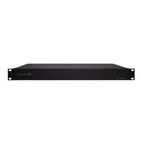
Control4 CORE-5 Controller
Installation Guide
Supported model
• C4-CORE5
Control4 CORE-5 Hub & Controller
Box contents
The following items are included in the box:
• CORE-5 controller
• AC power cord
• IR emitters (8)
• Rack ears (2, pre-installed on the CORE-5)
• Rubber feet (2, in box)
• External antennas (2)
• Terminal blocks for contacts and relays
Accessories sold separately
• Control4 3-Meter Wireless Antenna Kit (C4-AK-3M)
• Control4 Dual-Band WiFi USB Adapter (C4-USBWIFI OR C4-USBWIFI-1)
• Control4 3.5 mm to DB9 Serial Cable (C4-CBL3.5-DB9B)
Warnings
Caution! To reduce the risk of electrical shock, do not expose this
apparatus to rain or moisture.
Avertissement ! Pour réduire le risque de choc électrique, n'exposez
pas cet appareil à la pluie ou à l'humidité.
Caution! In an over-current condition on USB or contact output the
software disables the output. If the attached USB device or contact
sensor does not appear to power on, remove the device from the
controller.
Avertissement ! Dans une condition de surintensité sur USB ou sortie
de contact le logiciel désactive sortie. Si le périphérique USB ou
le capteur de contact connecté ne semble pas s'allumer, retirez le
périphérique du contrôleur.
Caution! If this product is used as a means to open and close a
garage door, gate, or similar device, use safety or other sensors
to ensure safe function. Follow appropriate regulatory and safety
standards governing project design and installation. Failure to do so
may result in property damage or personal injury.
Requirements and specifications
Note: We recommend using Ethernet instead of WiFi for the best
network connectivity.
Note: The Ethernet or WiFi network should be installed before you
install the CORE-5 controller.
Note: The CORE-5 requires OS 3.3 or higher.
Composer Pro is required to configure this device. See the Composer Pro User
Guide (
ctrl4.co/cpro-ug
) for details.
Specifications
Inputs / Outputs
1 video out—1 HDMI
Video out
Video
HDMI 2.0a; 3840x2160 @ 60Hz (4K); HDCP 2.2 and HDCP 1.4
Audio out
7 audio out—1 HDMI, 3 stereo analog, 3 digital coax
Audio playback formats
AAC, AIFF, ALAC, FLAC, M4A, MP2, MP3, MP4/M4A, Ogg
Vorbis, PCM, WAV, WMA
High-res audio playback
Up to 192 kHz / 24 bit
Audio in
2 audio in—1 stereo analog, 1 digital coax
Audio delay on audio in
Up to 3.5 seconds, depending on network conditions
Digital coax in—Input level
Digital signal processing
Audio out 1/2/3 (analog)—Balance, volume, loudness, 6-band
PEQ, mono/stereo, test signal, mute
Digital coax out 1/2/3—Volume, mute
Signal-to-noise ratio
<-118 dBFS
Total harmonic distortion
0.00023 (-110 dB)
Network
Ethernet
1 10/100/1000BaseT compatible port (required for controller
setup).
WiFi
Optional Dual-Band WiFi USB Adapter
(2.4 GHz, 5 Ghz, 802.11ac/b/g/n/a)
WiFi security
WPA/WPA2
ZigBee Pro
802.15.4
External reverse SMA connector
ZigBee antenna
Z-Wave
Z-Wave 700 series
Z-Wave antenna
External reverse SMA connector
USB port
2 USB 3.0 port—500mA
Control
IR OUT
8 IR out—5V 27mA max output
IR capture
1 IR receiver—front; 20-60 KHz
SERIAL OUT
4 Serial out—2 DB9 ports and 2 shared with IR out 1-2
Contact
4 contact sensors—2V-30VDC input,
12VDC 125mA maximum output
4 relays—AC: 36V, 2A maximum voltage across relay;
Relay
DC: 24V, 2A maximum voltage across relay
Power
Power requirements
100-240 VAC, 60/50Hz
Power consumption
Max: 40W, 136 BTUs/hour
Idle: 15W, 51 BTUs/hour
Other
Operating temperature
32˚F × 104˚F (0˚C × 40˚C)
4˚F × 158˚F (-20˚C × 70˚C)
Storage temperature
Dimensions (H × W × D)
1.65
×
17.4
×
9.92" (42
×
442
×
252 mm)
Weight
5.9 lbs (2.68 kg)
Shipping weight
9 lbs (4.08 kg)
Additional resources
The following resources are available for more support.
• Control4 CORE series help and information:
ctrl4.co/core
• Snap One Tech Community and Knowledgebase:
tech.control4.com
• Control4 Technical Support
• Control4 website:
www.control4.com
Front view
A B C D E
A Activity LED—The LED indicates that the controller is streaming audio.
B IR window—IR receiver for learning IR codes.
C Caution LED—This LED shows solid red, then blinks blue during the boot
process.
Note: The Caution LED flashes orange during the factory restore
process. See "Reset to factory settings" in this document.
D Link LED—The LED indicates that the controller has been identified in a
Control4 Composer project and is communicating with Director.
E Power LED—The blue LED indicates that AC power is connected. The
controller turns on immediately after power is applied to it.
Back view
A
B
C D E F
G
H
I
J
A Power plug port—AC power receptacle for an IEC 60320-C13 power cord.
B Contact/Relay port—Connect up to four relay devices and four contact
sensor devices to the terminal block connector. Relay connections are
COM, NC (normally closed), and NO (normally open). Contact sensor
connections are +12, SIG (signal), and GND (ground).
C ETHERNET—RJ-45 jack for a 10/100/1000 BaseT Ethernet connection.
D USB—Two port for an external USB drive or the optional Dual-Band WiFi
USB Adapter. See "Set up external storage devices" in this document.
E HDMI OUT—An HDMI port to display system menus. Also an audio out over
HDMI.
F ID and FACTORY RESET—ID button to identify the device in Composer Pro.
The ID button on the CORE-5 is also an LED that displays feedback useful
during a factory restore.
G ZWAVE—Antenna connector for the Z-Wave radio
H SERIAL—Two serial ports for RS-232 control. See "Connecting the serial
ports" in this document.
I
IR / SERIAL—Eight 3.5 mm jacks for up to eight IR emitters or for a
combination of IR emitters and serial devices. Ports 1 and 2 can be
configured independently for serial control or for IR control. See "Setting up
IR emitters" in this document for more information.
J
DIGITAL AUDIO—One digital coax audio input and three output ports.
Allows audio to be shared (IN 1) over the local network to other Control4
devices. Outputs audio (OUT 1/2/3) shared from other Control4 devices or
from digital audio sources (local media or digital streaming services such
as TuneIn.)
K ANALOG AUDIO—One stereo audio input and three output ports. Allows
audio to be shared (IN 1) over the local network to other Control4 devices.
Outputs audio (OUT 1/2/3) shared from other Control4 devices or from
digital audio sources (local media or digital streaming services such as
TuneIn.)
L ZIGBEE—Antenna for the Zigbee radio.
Installing the controller
To install the controller:
1
Ensure that the home network is in place before starting system setup.
The controller requires a network connection, Ethernet (recommended)
or WiFi (with optional adapter), to use all of the features as designed.
When connected, the controller can access web-based media databases,
communicate with other IP devices in the home, and access Control4
system updates.
2 Mount the controller in a rack or stacked on a shelf. Always allow plenty
of ventilation. See "Mounting the controller in a rack" in this document.
3 Connect the controller to the network.
• Ethernet—To connect using an Ethernet connection, plug the data
cable from the home network connection into the controller's RJ-45
port (labeled ETHERNET) and the network port on the wall or at the
network switch.
• WiFi—To connect using WiFi, first connect the controller to Ethernet,
and then use Composer Pro System Manager to reconfigure the
controller for WiFi.
4 Connect system devices. Attach IR and serial devices as described in
"Connecting the IR ports/serial ports" and "Setting up IR emitters."
5 Set up any external storage devices as described in "Setting up external
storage devices" in this document.
6 Power up the controller. Plug the power cord into the controller's power
plug port and then into an electrical outlet.
Mounting the controller in a rack
Using the pre-installed rack-mount ears, the CORE-5 can easily be mounted
in a rack for convenient installation and flexible rack placement. The pre-
installed rack-mount ears can even be reversed to mount the controller facing
the rear of the rack, if needed.
To attach the rubber feet to the controller:
K
L
1
Remove the two screws in each of the rack ears on the bottom of the
controller. Remove the rack ears from the controller.
2 Remove the two additional screws from the controller case and place the
rubber feet on the controller. .
3 Secure the rubber feet to the controller with three screws in each rubber
foot.
Pluggable terminal block connectors
For the contact and relay ports, the CORE-5 makes use of pluggable terminal
block connectors which are removable plastic parts that locks in individual
wires (included).
To connect a device to the pluggable terminal block:
1
Insert one of the wires required for your device into the appropriate
opening in the pluggable terminal block you reserved for that device.
2 Use a small flat-blade screwdriver to tighten the screw and secure the
wire in the terminal block.
Example: To add a motion sensor (see Figure 3), connect its wires
to the following contact openings:
• Power input to +12V
• Output signal to SIG
• Ground connector to GND
Note: To connect dry contact closure devices, such as doorbells,
connect the switch between +12 (power) and SIG (signal).
Advertisement

Subscribe to Our Youtube Channel
Related Manuals for Control 4 CORE-5


Summary of Contents for Control 4 CORE-5
- Page 1 8 IR out—5V 27mA max output block connectors which are removable plastic parts that locks in individual Warnings The ID button on the CORE-5 is also an LED that displays feedback useful wires (included). IR capture 1 IR receiver—front; 20-60 KHz during a factory restore.
- Page 2 1 Press and hold the ID button for five seconds. The controller turns off and The CORE-5 controller provides four serial ports. SERIAL 1 and SERIAL 2 can blocks. See the examples below to learn how to connect devices to the contact connect to a standard DB9 serial cable.
- Page 3 Regulatory Compliance & Safety Information for Model C4-CORE5 Electrical Safety Advisory Sécurité électrique consultatif Important Safety Instructions Consignes de sécurité importantes Read the safety instructions before using this product. Lisez les consignes de sécurité avant d'utiliser ce produit. 1. Read these instructions. Lisez ces instructions.
- Page 4 11. Refer all servicing to qualified service personnel. Servicing is required when the apparatus has been damaged in any way, such as power-supply cord or plug is damaged, liquid has been spilled or objects have fallen into the apparatus, the apparatus has been exposed to rain or moisture, does not operate normally, or has been dropped.
- Page 5 This product requires a properly grounded outlet for safety. This plug is designed to be inserted into a NEMA 5-15 (three-prong grounded) outlet only. Do not force the plug into an outlet that is not designed to accept it. Never dismantle the plug or alter the power cord, and do not attempt to defeat the grounding feature by using a 3-to-2 prong adapter.
- Page 6 WARNING – No user serviceable parts inside. If the product is not operating properly, do not remove any part of the unit (cover, etc.) for repair. Unplug the unit and consult the warranty section of the owner’s manual. AVERTISSEMENT – Aucune pièce réparable par l'utilisateur à l'intérieur. Si le produit ne fonctionne pas correctement, ne retirez aucune pièce de l'appareil (couvercle, etc.) pour réparation.
- Page 7 AVERTISSEMENT! Pour réduire le risque de choc électrique, n'exposez pas cet appareil à la pluie ou à l'humidité. Save these instructions Conservez ces instructions Compliance of this equipment is confirmed by the following label that is placed on the equipment: Conformité...
- Page 8 Innovation Science and Economic Development (ISED) Unintentional Emissions Interference Statement This device contains licence-exempt transmitter(s)/receiver(s) that comply with Innovation, Science and Economic Development Canada’s licence-exempt RSS(s). Operation is subject to the following two conditions: (1) This device may not cause interference (2) This device must accept any interference, including interference that may cause undesired operation of the device L’émetteur/récepteur exempt de licence contenu dans le présent appareil est conforme aux CNR...
-
Page 9: Rf Radiation Exposure Statement
le gain maximal d'antenne permis (pour les dispositifs utilisant la bande de 5725 à (ii) 5 850 MHz) doit être conforme à la limite de la p.i.r.e. spécifiée pour l'exploitation point à point et l’exploitation non point à point, selon le cas; (iii) De plus, les utilisateurs devraient aussi être avisés que les utilisateurs de radars de haute puissance sont désignés utilisateurs principaux (c.-à-d., qu’ils ont la priorité) pour les bandes 5650-5850 MHz et que ces radars pourraient causer du brouillage et/ou des dommages aux... -
Page 10: Weee Compliance
The frequency and maximum transmitted power in EU are listed as below: 2412 - 2472 MHz: ?$ dBm 5180 - 5240 MHz: ?$ dBm WLAN 5GHz: Operations in the 5.15-5.35GHz band are restricted to indoor usage only. United Kingdom (UK) Compliance Compliance of this equipment is confirmed by the following logo that is placed on the product ID label that is placed on the bottom of the equipment. -
Page 11: About This Document
Australia & New Zealand Compliance Compliance of this equipment is confirmed by the following logo that is placed on the product ID label that is placed on the bottom of the equipment. About this Document Copyright © 2022 Snap One All rights reserved. 1800 Continental Blvd.
Need help?
Do you have a question about the CORE-5 and is the answer not in the manual?
Questions and answers