Advertisement
Quick Links
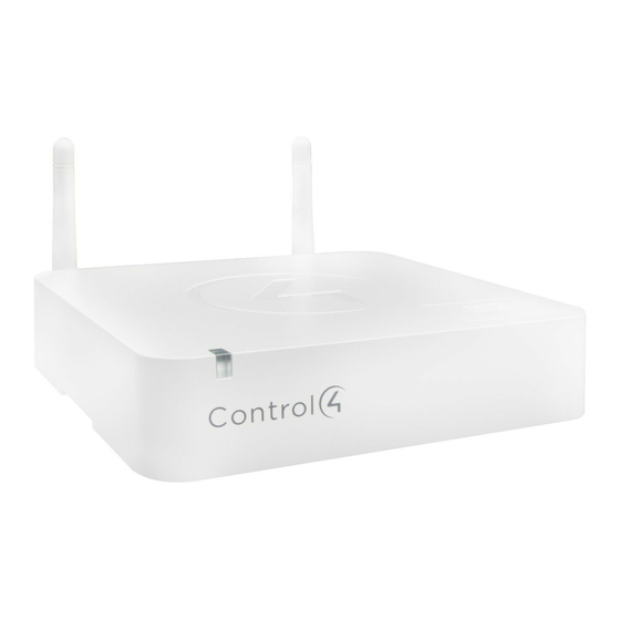
CA-1 Hub and Automation Controller, V2
Installation Guide
Supported model
•
C4-C A1-V2
Hub &
Automation Controller, CA-1, V2
Introduction
The Control4® CA-1 Hub & Automation Controller enables control of lights, security
systems, sensors, door locks, and other devices controlled by IP, Zigbee, Z-Wave®, or serial
connections. The controller has a fast processor, external antenna for Zigbee® radio, an
internal slot for a Z-Wave™ module (sold spearately), and can be powered by PoE. This
controller is perfect for home, apartments, and other installations that do not require IR
control or audio streaming.
After you install and configure the controller with other Control4 devices, your customers
can control their system using the Control4 apps, system remote controls, touch screens,
or other Control4-supported interface devices (sold separately).
Box contents
•
CA-1 Hub & Automation Controller, V2
•
External power supply with international plug adaptors
•
Antennas (1 for Zigbee)
Accessories available for purchase
•
Z-Wave Module - Region H (C4-ZWH)
•
Z-Wave Module - Region U (C4-ZWU)
•
Z-Wave Module - Region E (C4-ZWE)
Warnings
Caution! To reduce the risk of electrical shock, do not expose this apparatus to
rain or moisture.
AVERTISSEMENT ! Pour réduire le risque de choc électrique, n'exposez pas cet
appareil à la pluie ou à l'humidité.
Caution! In an over-current condition on USB, the software disables the
output. If the attached USB device does not appear to power on, remove the
USB device from the controller.
AVERTISSEMENT ! Dans une condition de surintensité sur USB le logiciel
désactive la sortie. Si le périphérique USB connecté ne semble pas s'allumer,
retirez le périphérique du contrôleur.
Requirements and specifications
Note: The Ethernet should be installed before starting the CA-1 controller
installation.
Note: The software required to configure this device is Composer Pro. See the
Composer Pro User Guide (ctrl4.co/cpro-ug) for details.
Specifications
Model number
C4-CA1-V2
Connections
Network
Ethernet—10/100BaseT compatible (required for controller setup)
Zigbee Pro
802.15.4
Zigbee antenna
External reverse SMA connector
USB port
2 USB 2.0 ports-500mA
Serial out
1 serial out RJ45 port (RS-232)
Z-Wave
Integrated Z-Wave slot accepts Control4 Z-Wave modules (sold
separately)
Music services
Requires Triad One for audio output. Does not support Spotify
Connect, ShairBridge, or My Music scanning.
Power
Power requirements
5V DC 3A, external power supply included
Power supply
AC power supply accepts 100-240V at 50-60 Hz (0.5A)
PoE
802.3af (<13W)
Power consumption
Max 15W (51 BTU/hr)
Miscellaneous
Operating temperature
32˚ - 104˚ F (0˚ - 40˚ C)
Storage temperature
4˚ - 158˚ F (-20˚ - 70˚ C)
Dimensions (L x W x H)
×
×
5.5"
5.5"
1.25" (14 × 14 × 3.8 cm)
Weight
0.65 lb (0.3 kg)
Shipping weight
1.5 lb (0.68 kg)
Additional resources
The following resources are available for more support.
•
Control4 Knowledgebase and Tech Community:
ctrl4.co/tc
•
Control4 Technical Support:
ctrl4.co/techsupport
•
Control4 website:
www.control4.com
•
Composer Pro documentation in online help or PDF format available on the Dealer
Portal under Support:
ctrl4.co/docs
•
Z-Wave documentation:
ctrl4.co/z-wave
Front view
A
A
Status LED—The RGB status LED gives system status feedback. See "Troubleshooting"
in this document for LED status information.
B
Z-Wave port—Removable plastic cover on top of the controller with a Z-Wave port
underneath for a Control4 Z-Wave module.
Back view
A
B
C
D
A
Zigbee—External antenna connector for Zigbee radio.
B
Power port—Power connection for external power supply.
C
ETHERNET (PoE)—RJ-45 port for 10/100BaseT Ethernet network connection. Network
connection used for configuration and device control. Supports PoE.
D
SERIAL—RJ-45 port for serial communications. Can be used for RS-232 communication
for device control.
E
USB—Two USB 2.0 ports for external USB drives (e.g., FAT32-formatted devices). See
"Setting up external storage devices" in this document.
F
ID / RESET buttons—Buttons used to identify the device in Composer Pro and reset the
controller. See "Troubleshooting" in this document.
Installing the controller
Requirements:
•
Ensure that the home network is in place before starting system setup.
•
A wired connection to the network is required for initial controller setup.
•
The controller requires a network connection to use all of the features as designed.
When connected, the controller can communicate with other IP devices in the home
and access Control4 system updates.
•
Composer Pro software version 2.10.0 or newer is required for configuration.
Mounting options:
•
On-wall—The controller can be mounted to the wall using screws. Remove the
rubber feet, measure the distance between them, and insert 2 screws into the wall
so that the heads are about 1/4 to 1/2 inch from the wall. Position the holes on the
back of the controller over the screw heads and slide the controller onto the screws.
•
DIN rail—The controller can be mounted to the wall using a section of DIN rail
channel. Mount the rail to the wall, and then attach the controller to the rail.
Important: The CA-1 is not rated to be installed inside an electrical panel. DIN-
rail installation is only intended for a wall-mount or other section of DIN rail
outside of an electrical panel.
Connecting the controller
1 Connect the controller to the network by plugging a network cable into the
controller's RJ-45 port (labeled Ethernet (PoE)) from the network port on the wall or
at the network switch.
2 Attach serial devices as described in "Connecting the serial port." Serial port is only
used for controlling external devices, the controller must be connected over Ethernet
to set up the Control4 programming.
3 Connect any external storage devices (USB) as described in "Setting up external
B
storage devices" in this document.
4 Connect the power cord to the controller's power port and then into an electrical
outlet (if the controller is not powered by PoE).
Connecting the serial port (optional)
The controller includes one RJ-45 serial port that can be configured for RS-232 serial
communication.
The following serial communication configurations are supported:
•
RS-232—Hardware flow control, up to 115,200 Kbps.
(TXD, RXD, CTS, RTS, GND)
To set up the serial port:
1 Connect a serial device to the controller using Cat5/Cat6 cable and an RJ-45
connector.
Important: The serial port pinout follows the EIA/TIA-561 serial wiring
standard. Use the wiring shown in the diagram below. Many pre-built DB9 to
RS-232 cables, including network switch console cables, will not work.
2 To configure the serial port settings, make the appropriate connections in your
project using Composer Pro. See the Composer Pro User Guide for details.
Note: Serial settings are defined in the device driver in Composer. Serial
settings (baud, parity, and serial port type) are automatically configured when
E
F
a device driver is connected in Composer Pro to the serial port connection of
the CA-1 driver.
Serial port pinout and wiring recommendation
RS-232 pinout
ZIGBEE
EIA-561 wiring recommended
DB9 rear view
5
4
3
2
1
9
8
7
6
ETHERNET
Pins 1-3 not used
Pin 4 SG
Pin 5 RXD
Pin 6 TXD
Pin 7 CTS
Pin 8 RTS
Advertisement

Related Manuals for Control 4 CA-1


Summary of Contents for Control 4 CA-1
- Page 1 Mount the rail to the wall, and then attach the controller to the rail. AVERTISSEMENT ! Pour réduire le risque de choc électrique, n’exposez pas cet Important: The CA-1 is not rated to be installed inside an electrical panel. DIN- appareil à la pluie ou à l’humidité.
- Page 2 USB-powered external hard drives are not supported. Reset check Update error Note: When using USB storage devices with the CA-1 controller you can only use one partition with a 2TB maximum size. This limitation applies to USB storage devices with all other controllers also.
Need help?
Do you have a question about the CA-1 and is the answer not in the manual?
Questions and answers