Advertisement
Quick Links
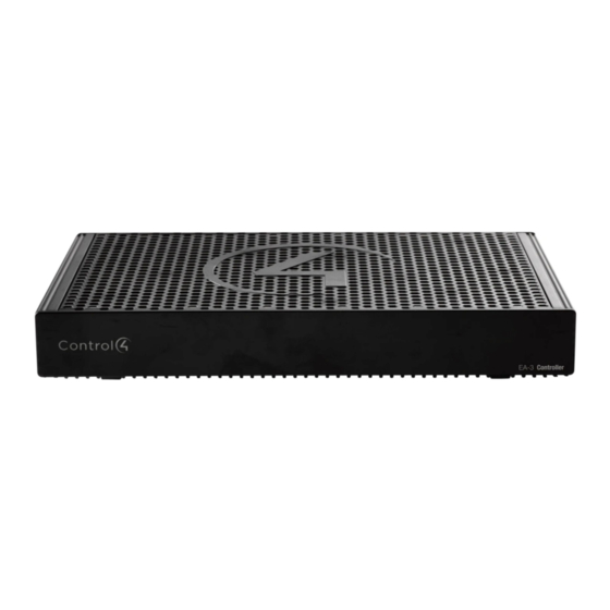
Control4 EA-3 Controller
Installation Guide
Supported models
• C4-EA3
Entertainment and Automation Controller, 3 Zone
• C4-EA3-V2
Entertainment and Automation Controller, 3 Zone, V2
Introduction
The versatile Control4 EA-3 Entertainment and Automation Controller is
the perfect fusion of multi-room, high-resolution audio and smart home
automation for small to mid-size homes.
Powered by a next-generation multi-core processor, the EA-3 delivers
a new level of speed and performance for instantaneous, interactive
on-screen access to all the systems in the home. A built-in music server
with three audio outputs delivers high-resolution audio throughout
the home from your local music library, popular streaming music
services, and AirPlay-enabled devices using native Control4 ShairBridge
technology.
The EA-3 includes a variety of I/O to automate audio and video,
lighting, climate control, door locks, and other devices controlled by
IP, infrared (IR), serial, and ZigBee. With PoE+ for power, a port for
Ethernet out, and an optional mounting bracket, the compact form
factor of the EA-3 makes it easy to install behind any TV or projector.
Box contents
The following items are included in the box:
• EA-3 controller
• AC power cord
• IR emitters (6)
• External antennas (1 EA-3 V2, 2 EA-3 V1)
• Terminal block for contacts and relays
Accessories sold separately
• Control4 3.5 mm-to-DB9 Serial Cable (C4-CBL3.5-DB9B)
• 1U Rack-Mount Kit, Single EA-3 Controller (C4-EA3RMK1-BL)
• 1U Rack-Mount Kit, Dual EA-3 Controllers (C4-EA3RMK2-BL)
• EA-3 Wall-Mount Bracket (C4-WMEA3)
• Dual-Band WiFi USB Adapter (C4-USBWIFI or C4-USBWIFI-1)
Warnings
Caution! To reduce the risk of electrical shock, do not expose
this apparatus to rain or moisture.
Avertissement ! Pour réduire le risque de choc électrique,
n'exposez pas cet appareil à la pluie ou à l'humidité.
Caution! In an over-current condition on USB or contact
output the software disables the output. If the attached USB
device or contact sensor does not appear to power on, remove
the device from the controller.
Avertissement ! Dans une condition de surintensité sur USB ou
sortie de contact le logiciel désactive sortie. Si le périphérique
USB ou le capteur de contact connecté ne semble pas
s'allumer, retirez le périphérique du contrôleur.
Requirements and specifications
Note: We recommend using Ethernet instead of WiFi for the
best network connectivity.
Note: The Ethernet or WiFi network should be installed before
you install the EA-3 Controller.
Note: The EA-3 V2 requires OS 2.10.2 or higher. The EA-3 V1
requires OS 2.8.1 or higher.
Composer Pro is required to configure this device. See the Composer
Pro User Guide (ctrl4.co/cpro-ug) for details.
Specifications
Inputs / outputs
Video out
1 video out—1 HDMI
Video
HDMI 1.4 output; HD 1080p, 50-60 Hz
Audio out
3 audio outputs—1 HDMI, 1 stereo analog (3.5 mm),
1 digital coax
Audio in
2 network-encoded audio inputs—1 stereo analog
(3.5 mm), 1 digital coax
Audio delay on audio in
Up to 3.5 seconds, depending on network conditions
Audio playback formats
AAC, AIFF, ALAC, FLAC, M4A, MP2, MP3, MP4/M4A,
Ogg Vorbis, PCM, WAV, WMA
High-resolution audio playback
Up to 192 kHz / 24 bit
Advanced audio subsystem
Dedicated audio signal processor
Audio system controls (analog
10-band graphic equalizer, input gain, output gain,
loudness, tone controls, balance
only)
Signal-to-noise ratio
<-110 dBFS
Total harmonic distortion
0.0015 (-96.5 dB)
Network
Ethernet
10/100/1000BaseT compatible (required for
controller setup). PoE+ supported.
Power over Ethernet
802.3at-2009 (PoE+) / 25.5W
Built-in Ethernet switch
1 Ethernet/PoE in + 1 Ethernet switch port
WiFi
Internal Dual-Band Wireless-N (EA-3 V1)
(2.4GHz, 5GHz, 802.11n/g/b)
Optional Dual-Band WiFi USB Adapter (EA-3 V2)
(2.4 GHz, 5 Ghz, 802.11ac/b/g/n/a)
WiFi security
WPA/WPA2
WiFi antenna
External reverse SMA connector (EA-3 V1 only);
optional WiFi adapter on the EA-3 V2
ZigBee Pro
802.15.4
ZigBee antenna
External reverse SMA connector
USB port
1 USB 2.0 port—500mA minimum
Control
IR OUT
6 IR out—5V 27mA max output
1 IR blaster—front
IR capture
1 IR receiver—front; 20-60 KHz
SERIAL OUT
3 serial out (shared with IR out 1-3)
Contact
1 contact sensor—2V-30VDC input,
12VDC 125mA maximum output
Relay
1 relay—AC: 36V, 2A maximum voltage across relay;
DC: 24V, 2A maximum voltage across relay
Power
Power requirements
100-240 VAC, 60/50Hz or PoE+
Power consumption
Max: 18W, 61 BTUs/hour
Idle: 9W, 30 BTUs/hour
Other
Operating temperature
32˚F ~ 104˚F (0˚C ~ 40˚C)
Storage temperature
4˚F ~ 158˚F (-20˚C ~ 70˚C)
Fan dB level
Max: 35 dB
Dimensions (H × W × D)
8.75 × 5.875 × 1.25" (221 × 149 × 31 mm)
Weight
1.60 lbs (0.74 kg)
Shipping weight
2.75 lbs (1.26 kg)
Additional resources
The following resources are available for more support.
• Control4 Knowledgebase:
kb.control4.com
and Dealer Forums:
forums.control4.com
• Control4 Technical Support
• Control4 website:
www.control4.com
• Composer Pro documentation in online help or PDF format available
on the Dealer Portal under Support:
ctrl4.co/docs
Front view
A
B
C
A Data LED—The LED indicates that the controller is streaming audio.
B IR window—IR blaster and IR receiver for learning IR codes.
C Caution LED—This LED shows solid red, then blinks blue during the
boot process.
Note: The Caution LED flashes orange during the factory
restore process. See "Reset to factory settings" in this
document.
D Link LED—The blue LED indicates that the controller has been
identified in a Control4 Composer project and is communicating with
Director.
E Power LED—The blue LED indicates that AC power is connected. The
controller turns on immediately after power is applied to it.
Back view
A
B
C
D
E F G
H
I
J
K
L
A WIFI—Reverse SMA connector for WiFi antenna (EA-3 V1 only).
B Power plug port—AC power receptacle for an IEC 60320-C5 power
cord.
C Contact/Relay port—Connect one relay device and one contact
sensor device to the terminal block connector. Relay connections are
COM, NC (normally closed), and NO (normally open). Contact sensor
connections are +12, SIG (signal), and GND (ground).
D Serial and IR OUT—3.5 mm jacks for up to six IR emitters or for a
combination of IR emitters and serial devices. Ports 1, 2, and 3 can
be configured independently for serial control or for IR control. See
"Connect IR/serial ports" in this document for more information.
E DIGITAL COAX IN—Allows audio to be shared over the local network
to other Control4 devices.
F AUDIO IN and OUT—Stereo audio input and output ports (3.5 mm
stereo audio jack). Allows audio to be shared (AUDIO IN) over the
local network to other Control4 devices. Outputs audio (AUDIO
OUT) shared from other Control4 devices or from digital audio
sources (local media or digital streaming services such as TuneIn).
G DIGITAL COAX OUT—Outputs audio (AUDIO OUT) shared from
other Control4 devices or from digital audio sources (local media or
digital streaming services such as TuneIn).
H HDMI OUT—An HDMI port to display navigation menus. Also an
audio out over HDMI.
I
ID button—Button to identify the device in Composer Pro. The ID
button on the EA-3 V2 is also an LED that displays feedback useful
during a factory restore.
J FACTORY RESTORE—Used to restore the controller to its factory
defaults.
K USB—One port for an external USB drive, or, on an EA-3 V2, the
optional Dual-Band WiFi USB Adapter. See "Setting up external
storage devices" in this document.
L Ethernet—Ethernet port that can be used as a network switch to
connect another local Ethernet device to the network.
M Ethernet/POE—RJ-45 jack for a 10/100/1000 BaseT Ethernet
connection. Use this port as the 'uplink port' to your local network. If
using PoE+ to power the controller, this port must be used.
N ZIGBEE—Reverse SMA connector for ZigBee antenna.
Installing the controller
To install the controller:
1
Ensure that the home network is in place before starting system
setup. The controller requires a network connection—Ethernet
(recommended) or WiFi—to use all of the features as designed.
When connected, the controller can access web-based media
databases, communicate with other IP devices in the home, and
access Control4 system updates.
2 Mount the controller behind a TV, on a wall, placed in a rack, or
stacked on a shelf. See "Mounting the controller behind a TV or on
the wall" below if mounting the controller on a wall or behind a TV.
3 Attach antennas to the WIFI and ZIGBEE antenna connectors and
for an EA-3 V2 controller, connect the optional WiFi USB Adapter
to the USB port if WiFi connectivity is needed.
D
E
4 Connect the controller to the network.
• Ethernet—To connect using an Ethernet connection, plug the data
cable from the home network connection into the controller's RJ-
45 port (labeled "ETHERNET/POE") and the network port on the
wall or at the network switch. An additional Ethernet-connected
device can be connected to the Ethernet Out RJ-45 port.
Note: If using PoE+ to power the controller, make all
connections prior to plugging in the PoE injector or switch.
• WiFi—To connect using WiFi, first connect the controller to
Ethernet, and then use Composer Pro System Manager to
reconfigure the controller for WiFi.
Important: Do not install your EA controller on a
172.18.xxx.xxx subnet.
5 Connect system devices such as IR and serial devices as described
in "Connect the IR ports/serial ports" and "Set up IR emitters."
6 Set up any external storage devices as described in "Setting up
external storage devices" in this document.
7 Connect the power cord to the controller's power port and then
M
N
into an electrical outlet, or for a PoE connection, power on the
PoE+-enabled network switch or PoE+ injector.
Mounting the controller behind a TV or on the wall
Using the optional Wall-Mount Bracket (C4-WMEA3), the EA-3 can
easily be mounted behind a TV, on the wall using a 1- or 2-gang wall
box, or mounted directly on the wall. See the EA-3 Wall-Mount Bracket
Installation Guide (ctrl4.co/ea-wmb) for details.
Pluggable terminal block connectors
For the contact and relay ports, the EA-3 makes use of terminal block
connectors which are removable plastic parts that screw down to
secure individual wires (included).
To connect a device to the terminal block:
1
Insert one of the wires required for your device into the appropriate
opening in the pluggable terminal block you reserved for that
device (see Figure 3).
2 Insert the wire into the appropriate terminal connection and use a
small, flat-blade screwdriver to tighten the screw and secure the
wire.
Example: If you add a motion sensor (see Figure 5), connect
its wires to the following contact openings:
Power input to +12V
Output signal to SIG
Ground connector to GND
Tip: To connect a dry contact closure device, such as a
doorbell button, connect the wires from the button to
+12V (Power) and SIG (Signal).
Advertisement

Subscribe to Our Youtube Channel
Related Manuals for Control 4 C4-EA3-V2


Summary of Contents for Control 4 C4-EA3-V2
- Page 1 45 port (labeled “ETHERNET/POE”) and the network port on the (3.5 mm), 1 digital coax boot process. wall or at the network switch. An additional Ethernet-connected • C4-EA3-V2 Entertainment and Automation Controller, 3 Zone, V2 Note: The Caution LED flashes orange during the factory Audio delay on audio in Up to 3.5 seconds, depending on network conditions...
- Page 2 Connecting the contact port Connecting the IR ports/serial ports (optional) Power cycle the controller The EA-3 provides one contact port on the included pluggable terminal The controller provides six IR ports. Ports 1, 2, and 3 can be 1 Press and hold the ID button for five seconds. The controller turns block (+12, SIG, GRD).
- Page 3 Regulatory Compliance & Safety Information for Control4 Model C4-EA3-V2 Electrical Safety Advisory Sécurité électrique consultatif Important Safety Information Informations de sécurité importantes Read the safety instructions before using this product. Lisez les consignes de sécurité avant d'utiliser ce produit. 1. Read these instructions.
- Page 4 10. Protect the power cord from being walked on or pinched particularly at plugs, convenience receptacles, and the point where they exit from the apparatus. 10. Protégez le cordon d'alimentation ne soit piétiné ou pincé, en particulier au niveau des fiches, des prises et au point où...
- Page 5 17. This product relies on the buildings installation for short-circuit (overcurrent) protection. Ensure that the protective device is rated not greater than: 20A. Ce produit repose sur l'installation des bâtiments pour les courts-circuits (surintensité) de protection. Assurez-vous que le dispositif de protection est assignée ne dépassant pas: 20A.
- Page 6 Save these instructions Conservez ces instructions Compliance of this equipment is confirmed by the following label that is placed on the equipment: Conformité de cet appareil est confirmé par le symbole suivant qui est placé sur l'équipement: USA & Canada Compliance FCC Part 15, Subpart B Unintentional Emissions Interference Statement This equipment has been tested and found to comply with the limits for a Class B digital device, pursuant to Part 15 of the FCC rules.
-
Page 7: Can Ices-3(B)/Nmb-3(B)
Notice: The term “FCC ID:” and “IC:” before the certification number signifies that FCC and Industry Canada technical specifications were met. C4-EA3-V2: FCC ID: R33C4EA3V2 IC: 7848A-C4EA3V2 This equipment must be installed by qualified professionals or contractors in accordance with FCC Part 15.203 &... - Page 8 This radio transmitter has been approved by Industry Canada to operate with the antenna type listed below with the maximum permissible gain indicated. Antenna types not included in this list, having a gain greater than the maximum gain indicated for that type, are strictly prohibited for use with this device.
- Page 9 Recycling Control4 understands that a commitment to the environment is essential for a health life and sustainable growth for future generations. We are committed to supporting the environmental standards, laws, and directives that have been put in place by various communities and countries that deal with concerns for the environment.
- Page 10 Home Controller Brand: Control4 Model(s): C4-EA3-V2 Product Standard(s) to which Conformity of the Council Directive(s) is declared: EMC - 2014/30/EU “Electromagnetic Compatibility (EMC) Directive”: (Emissions) EN 55032:2015 (Immunity) EN 55024:2010+A1:2015, EN 301 489-1 V1.9.2 (2011- 09), EN 301 489-17 V2.2.1 (2012-09), EN 61000-3-2:2014 & EN 61000-3-3:2013 Safety –...
- Page 11 Accueil Controller Marque: Control4 Modèle (s): C4-EA3-V2 Produit standard (s) dont la conformité de la directive du Conseil (s) est déclarée: EMC - 2014/30/EU "compatibilité électromagnétique (CEM)" UE: (Émissions) EN 55032:2015 (immunité) EN 55024:2010+A1:2015, EN 301 489-1 V1.9.2 (2011- 09), EN 301 489-17 V2.2.1 (2012-09), EN 61000-3-2:2014 & EN 61000-3-3:2013 Sécurité...
- Page 12 Home Controller Marke: Control4 Modell (e): C4-EA3-V2 Produkt-Norm (en), um die Konformität der Richtlinie (n) deklariert ist: EMC - 2014/30/EU "Elektromagnetische Verträglichkeit (EMV) Die Richtlinie": (Emissionen) EN 55032:2015 (Immunität) EN 55024:2010+A1:2015, EN 301 489-1 V1.9.2 (2011-09), EN 301 489-17 V2.2.1 (2012-09), EN 61000-3-2:2014 & EN 61000-3-3:2013 Sicherheit - 2014/35/EC "Niederspannungsrichtlinie (LVD)":...
- Page 13 Casa controller Marca: Control4 Modello (s): C4-EA3-V2 Prodotto standard (s) a cui conformità della direttiva del Consiglio (s) è dichiarato: EMC - 2014/30/EU "Compatibilità elettromagnetica (EMC)": (Emissioni) EN 55032:2015 (immunità) EN 55024:2010+A1:2015, EN 301 489-1 V1.9.2 (2011- 09), EN 301 489-17 V2.2.1 (2012-09), EN 61000-3-2:2014 & EN 61000-3-3:2013 Sicurezza - 2014/35/EC "Direttiva bassa tensione (LVD)":...
- Page 14 Controlador Inicio Marca: Control4 Modelo (s): C4-EA3-V2 Producto estándar (s) a la que la conformidad de la Directiva del Consejo (s) se declara: EMC - 2014/30/EU "Directiva de compatibilidad electromagnética (EMC)": (Emisiones) EN 55032:2015 (inmunidad) EN 55024:2010+A1:2015, EN 301 489-1 V1.9.2 (2011-09), EN 301 489-17 V2.2.1 (2012-09), EN 61000-3-2:2014 &...
- Page 15 Início Controlador Marca: Control4 Modelo (s): C4-EA3-V2 Padrão do produto (s) a que Conformidade da Directiva do Conselho (s) é declarado: EMC - 2014/30/EU "Compatibilidade Electromagnética (EMC)": (Emissões) EN 55032:2015 (Imunidade) EN 55024:2010+A1:2015, EN 301 489-1 V1.9.2 (2011- 09), EN 301 489-17 V2.2.1 (2012-09), EN 61000-3-2:2014 & EN 61000-3-3:2013 Segurança - 2014/35/EC "Directiva de Baixa Tensão (LVD)":...
Need help?
Do you have a question about the C4-EA3-V2 and is the answer not in the manual?
Questions and answers