General Titanium Series Instruction Manual
Optical level package
Hide thumbs
Also See for Titanium Series:
- Instruction manual (29 pages) ,
- Instruction manual (35 pages)

Related Manuals for General Titanium Series


Summary of Contents for General Titanium Series
- Page 1 T O L - 2 4 X O P T I C A L L E V E L P A C K A G E I N S T R U C T I O N M A N U A L...
- Page 2 SAFETY Read the following safety instructions before • P osition the optical level securely on a level attempting to operate this product. surface. Damage or serious injury could result if the optical level falls. Keep these instructions in a safe place or store in the carry case for future reference. • • SAVE ALL WARNINGS AND INSTRUCTIONS FOR FUTURE REFERENCE. • WARNING: Do Not Disassemble The Laser. WARNING: Read and understand all There are no user serviceable parts inside. instructions. Disassembling the laser will void all warranties on the product. Do not modify the product in any way. Modifying the tool may result in hazardous laser • U se only accessories that are recommended for radiation exposure. your model. • T ool service must be performed only by qualified repair personnel. Repairs, service or maintenance performed by unqualified personnel will void the warranty. Only approved and authorised service technicians can carry out warranty repairs.
-
Page 3: Item Checklist
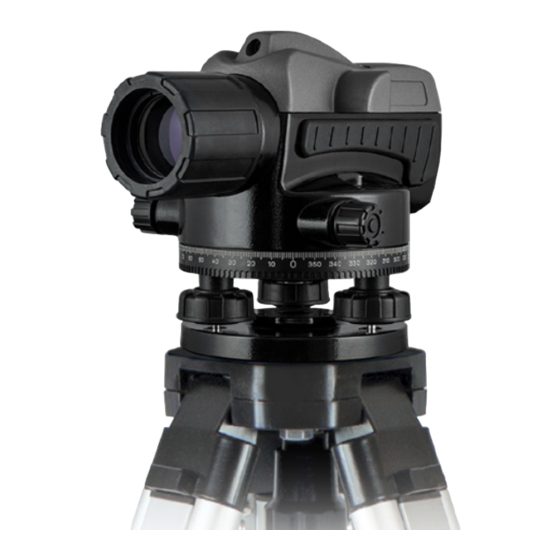
ITEM CHECKLIST Please ensure the following items are included with your laser level. If anything is missing please contact your retailer. Tripod Staff General Titanium Plumb bob Carry case Series TOL-24X... - Page 4 OPTICAL LEVEL OVERVIEW: FRONT Optical view guide Bubble vial mirror Front lens element Bubble vial Panning screw Panning screw 360° protractor Levelling screw Levelling screw 5/8” x 11 tripod thread Base plate...
- Page 5 OPTICAL LEVEL OVERVIEW: SIDE Optical view guide Focusing knob Eye piece Panning screw 360° protractor Levelling screw Levelling screw 5/8” x 11 tripod thread Base plate...
- Page 6 USING YOUR OPTICAL LEVEL SET UP OPERATION • S tand the tripod (part sold separately) on a level • Point the instrument towards the desired area. surface with legs spaced for stability. • Use a bright background or hold a white sheet of • T hread the tripod yoke through the 5/8” x 11 paper in front of the area. Turn the eyepiece until thread on the base of the instrument. Screw into the cross hairs are a sharp black. place until secure. • Turn the level towards the staff using the optical • Centre the bubble vial by turning the levelling view guide. screws. • Turn the panning screw to set the vertical hair down the centre of the staff. Measurement • Read the staff where it is cut by the middle hair.
- Page 7 USING YOUR OPTICAL LEVEL (continued) Distance measurement • Read the staff where it is cut by the upper and lower hairs. • Calculate the distance between the upper and lower hairs. • Multiply the figure by 100 to calculate the distance between the instrument and the staff. Angle measurement • Point the instrument towards the first point. • Set the protractor base to 0° • Point the instrument towards the second point. • The angle result will be in the protractor reading.
- Page 8 USING YOUR OPTICAL LEVEL (continued) Height measurement • S ubtract the measurement of staff B from staff A. (Example. 1.924m – 1.712m = 0.212m). This • Place the instrument onto a solid tripod calculation shows that staff B is 0.212m higher between two staves. than staff A. • Level off the optical using the bubble vial. • Take an accurate measurement reading from staff A. (Example. 1.924m). Take an accurate measurement reading from staff B (Example. 1.712m) 1.712m 1.924m 0.212m...
-
Page 9: Checking Accuracy
CHECKING ACCURACY BUBBLE VIAL COMPENSATOR • Centre the bubble by adjusting the levelling screws • P lace the instrument onto a solid tripod between until level. two staves spaced 30m to 50m apart. • Turn the instrument 90° at a time and check • Level off the optical using the bubble vial. the position of the bubble inside the vial. If the • Take an accurate measurement reading from bubble moves out of the centre ring a service and staff A. (Example. 1.924m). Take an accurate calibration is required. measurement reading from staff B (Example. 1.712m) • Subtract the measurement of staff B from staff A. (Example. 1.924m – 1.712m = 0.212m). This calculation shows that staff B is 0.212m higher than staff A. • Position the instrument and tripod 1m from Staff A while keeping it in between both Staff A and Staff B. • Take an accurate measurement reading from Staff A. (Example. 1.696m. Subtract the height difference that was calculated in step 3 from the current measurement reading (Example. 1.696m – 0.212m = 1.484m). - Page 10 CHECKING ACCURACY (continued) • Take an accurate measurement reading from staff • If the compensator accuracy is less or greater B. The measurement reading for staff B should be than 3mm after following the measurements and approximately 1.484m based on the calculation calculations shown in these steps, a service and above. calibration is required. 1.712m 1.924m (1.696m) (1.484m) 0.212m...
-
Page 11: Care And Maintenance
CARE AND MAINTENANCE • T his is a precision measuring instrument • C lean the instrument with a dry, soft cloth after and should always be handled with care and use in dusty, damp or wet conditions before transported within the carry case provided. storing. Use lens paper to clean the lens. Do not use your finger. • W henever possible, store the instrument in a dry, shady location. • S mudges and fingerprints may be removed with a damp tissue or a soft, lint-free cloth. • C alibration of the instrument is recommended: every six months, if ongoing accurate levelling is required, or an impact has occurred. • T he operator should check the accuracy of the instrument before precision levelling is attempted. Failure to do so may result in inaccurate measurements. -
Page 12: Warranty
WARRANTY 3 YEAR STANDARD WARRANTY PERIOD 7 YEAR EXTENDED WARRANTY PERIOD 1. The warranty period for your tool is 3 years from 1. T he extended warranty is available on selected the date of purchase. tools only. 2. T he warranty period for batteries, battery packs 2. Y ou may extend the warranty period for your and chargers is 1 year from the date of purchase. tool to 7 years from the date of purchase. This excludes batteries, battery packs and chargers. 3. C alibrations are not covered under warranty as they are deemed wear and tear. 3. C alibrations are not covered under warranty as they are deemed wear and tear. 4. A ll products have a standard warranty period, you do not have to register your products to obtain the 4. T o obtain the extended warranty, the registration standard warranty period. - Page 13 WARRANTY (continued) AUSTRALIA NEW ZEALAND “Our goods come with guarantees that cannot be For more information please visit excluded under the Australian Consumer Law. You consumerprotection.govt.nz are entitled to a replacement or refund for a major failure and for compensation for any other reasonably foreseeable loss or damage. You are also entitled to have the goods repaired or replaced if the goods fail to be of acceptable quality and the failure does not amount to a major failure.” For more information please visit consumerlaw.gov.au...
-
Page 14: Customer Support
CUSTOMER SUPPORT To assist you with any queries or technical questions please contact customer support Australia: 1300 658 338 New Zealand: 0800 367 527... -
Page 15: Specifications
SPECIFICATIONS Specifications TOL-24X Product code 88720 Warranty 7 Years* Accuracy ±2.5mm at 1km (double run) Compensator range 15’ Magnification Minimum focus Objective aperture Weight (kg) 1.385 Dimensions (mm) 135 x 210 x 150 *With online registration (3 years without registration). Please refer to page 12 for details. - Page 16 www.sp oton .com .au...
Need help?
Do you have a question about the Titanium Series and is the answer not in the manual?
Questions and answers