General Titanium Series Instruction Manual
Red rotary laser
Hide thumbs
Also See for Titanium Series:
- Instruction manual (29 pages) ,
- Instruction manual (17 pages)
Table of Contents
Advertisement
Quick Links
Advertisement
Table of Contents

Related Manuals for General Titanium Series


Summary of Contents for General Titanium Series
- Page 1 T R L - 6 0 R S R E D R O T A R Y L A S E R I N S T R U C T I O N M A N U A L...
- Page 2 SAFETY Read the following safety instructions before • Tool service must be performed only by qualified attempting to operate this product. repair personnel. Repairs, service or maintenance performed by unqualified personnel will void the Keep these instructions in a safe place or store in the warranty.
- Page 3 SAFETY (continued) CAUTION: Class 2 Laser Product • Do not let children come in contact with the laser. • Turn the laser off when it is not in use. Leaving • Never look into the laser beam directly and the laser on increases the risk of staring into the intentionally.
-
Page 4: Item Checklist
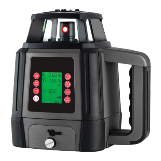
GRA D E AUTO AU TO G RAD E G RAD E TILT TI LT AL A RM A L A R M General Titanium Remote control Detector & clamp Laser target Laser glasses Series TRL-60RS AUTO AU TO G R ADE... - Page 5 LASER OVERVIEW: FRONT Protective lighthouse Rotating laser port LCD display screen M A NUA L MA N UAL G R A D E GRADE AUTO AU TO G R A D E GRA DE T I LT T ILT Control panel AL AR M AL AR M Battery compartment...
- Page 6 LASER OVERVIEW: BASE Battery compartment with rechargeable battery Carry handle 5/8” x 11 thread for horizontal operation on a tripod Padded feet for vertical operation on a flat surface...
- Page 7 LASER OVERVIEW: BACK Rotating laser port Carry handle 5/8” x 11 thread for vertical operation on a tripod Padded feet for vertical operation on a flat surface...
- Page 8 LASER OVERVIEW: CONTROL PANEL Manual / automatic mode Grade adjustment Counter clockwise rotation MANUAL Grade adjustment GRADE Clockwise rotation Dial-in grade mode AUTO GRADE Speed control Scanning mode Tilt alarm Power TIL T ALARM LCD display screen...
- Page 9 LASER OVERVIEW: LCD SCREEN X-axis Grade percentage Y-axis Grade percentage Scan mode setting (when scan mode is active) RPM rotation speed Scan mode Manual grade mode Self-levelling (flash) Automatic grade mode Battery level Tilt alarm...
- Page 10 REMOTE CONTROL OVERVIEW: FRONT LCD display screen Manual grade mode Grade adjustment Grade adjustment Clockwise rotation Counter clockwise rotation Automatic grade mode Scan mode Speed control Tilt alarm...
- Page 11 REMOTE CONTROL OVERVIEW: BACK Battery compartment...
- Page 12 REMOTE CONTROL OVERVIEW: LCD SCREEN X-axis Y-axis Rotation speed (RPM) Automatic grade mode Self-levelling Tilt alarm Manual grade mode Scan mode Battery level...
- Page 13 DETECTOR OVERVIEW: FRONT LED indicators Laser sensor LCD display screen Metric or imperial selection (press) Screen backlight (hold) Power on / off (detector) Detection mode Speaker on / off...
- Page 14 DETECTOR OVERVIEW: LCD SCREEN Measurement Plus and minus indicator Unit Arrow indicator Detection mode Centre alignment Arrow indicator Brightness indicator Speaker indicator Battery indicator...
- Page 15 DETECTOR OVERVIEW: BACK Speaker Staff clamp mounting point LCD display screen Battery compartment...
-
Page 16: Using Your Laser
USING YOUR LASER POWER SUPPLY Rechargeable battery pack • The instrument is supplied with a rechargeable Indoor charger / mains power adaptor Ni-MH battery pack that is located on the front of the instrument below the control panel. • The indoor charger is for indoor use only. •... - Page 17 USING YOUR LASER (continued) Charging the rechargeable battery pack Removing and inserting the rechargeable battery pack or alkaline battery pack • Insert the charger into the charging port on the rechargeable battery pack. Progress will be • Loosen the battery pack screw on the front of the shown by the power indicator display on the instrument below the control panel and slide the charger as below:...
- Page 18 USING YOUR LASER (continued) HORIZONTAL MEASUREMENT SET UP Tripod set up • Select a place as close and practical to the work Level surface set up site as possible, and ensure that the location is • Select a place as close and practical to the work clear of traffic.
- Page 19 USING YOUR LASER (continued) VERTICAL MEASUREMENT SET UP Tripod set up • Select a place as close and practical to the work Level surface set up site as possible, and ensure that the location is • Select a place as close and practical to the work clear of traffic.
-
Page 20: Operation
USING YOUR LASER (continued) OPERATION Speed control • Press the speed control button on the laser or Powering on remote control to cycle through various rotational speeds. • Press the power button once and the instrument will power on and begin automatically self- • The current rotation speed selected will be levelling. - Page 21 USING YOUR LASER (continued) Scanning mode Rotation direction • To focus the laser beam between two points press • Whilst the instrument is in scanning mode press the scanning mode button on the laser or remote the clockwise or counter clockwise button on the control.
- Page 22 USING YOUR LASER (continued) Setting up a dial-in grade / slope • The instrument will now adjust to your selected • To create a dial-in grade / slope, press the automatic grade mode button on the laser or grade(s) / slope(s). remote control.
- Page 23 USING YOUR LASER (continued) Setting up a manual grade / slope When in manual mode the instrument will not self level and correct for vibrations and/or • To create a manual grade / slope, press the disturbances. manual grade mode button. The instrument will now be in the X-axis manual grade mode as indicated by the LED on the laser control panel.
-
Page 24: Using Your Remote
USING YOUR REMOTE POWER SUPPLY REMOTE OPERATION • The remote is powered by two AA alkaline • Ensure the instrument is turned on and the laser batteries head is rotating. • Press the power button to turn on the remote control. -
Page 25: Using Your Detector
USING YOUR DETECTOR POWER SUPPLY DETECTOR OPERATION • Switch the detector on by pressing the power • The detector is powered by four AA alkaline batteries. button. The LCD screen will turn on and the speaker will emit a small tone to indicate the instrument is operating. - Page 26 USING YOUR DETECTOR (continued) Detector position for vertical beams Detector position for horizontal beams...
-
Page 27: Checking Calibration
CHECKING CALIBRATION Before doing any precision levelling it is advised to check the calibration of the instrument. • Set up the laser on a tripod at about 30m facing a wall or staff with a detector. • Allow the instrument to level. •... -
Page 28: Troubleshooting
TROUBLE SHOOTING Error Cause & Solution • Check the batteries. They may be in the wrong way or need replacing. Laser does not • Check the battery compartment for signs of damage. Ensure they are clean and not bent. turn on • Connect the mains power adaptor. -
Page 29: Care And Maintenance
CARE AND MAINTENANCE • Reflective surfaces such as glass may reflect the • The operator should check the accuracy of the beam, causing two beams to strike the detector instrument before precision levelling is attempted. at the same time. This may create inaccurate Failure to do so may result in inaccurate reference points. -
Page 30: Warranty
WARRANTY 3 YEAR STANDARD WARRANTY PERIOD 7 YEAR EXTENDED WARRANTY PERIOD 1. The warranty period for your tool is 3 years from 1. The extended warranty is available on selected the date of purchase. tools only. 2. The warranty period for batteries, battery packs 2. - Page 31 WARRANTY (continued) AUSTRALIA NEW ZEALAND “Our goods come with guarantees that cannot be For more information please visit excluded under the Australian Consumer Law. You consumerprotection.govt.nz are entitled to a replacement or refund for a major failure and for compensation for any other reasonably foreseeable loss or damage.
-
Page 32: Customer Support
CUSTOMER SUPPORT To assist you with any queries or technical questions please contact customer support Australia: 1300 658 338 New Zealand: 0800 367 527... -
Page 33: Specifications
SPECIFICATIONS Specifications TRL-60RS Product code 88150 Warranty 7 Years* Accuracy ±1mm at 30m Operating range 800m (diameter) Levelling range ±9% / ±5° Laser class 2 Red Battery life 20 hours+ IP rating Weight (kg) 3.99 (inc. battery) Dimensions (mm) 225 x 183 x 230 *With online registration. - Page 34 www.sp oton .com .au...
Need help?
Do you have a question about the Titanium Series and is the answer not in the manual?
Questions and answers