Advertisement
Quick Links
Operators Manual
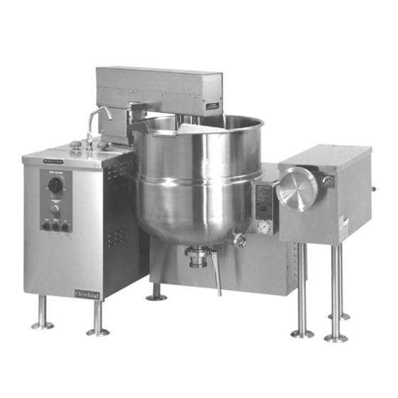
Gas Floor Model Vertical Mixer Kettles
MODELS:
MKGL-40-T
MKGL-60-T
MKGL-80-T
MKGL-100-T
™
Cleveland
Enodis
Installation, Operation & Service
For units built prior to July 2010
1333 East 179th St., Cleveland, Ohio, U.S.A. 44110
Phone: (216) 481-4900 Fax: (216) 481-3782
Visit our web site at www.clevelandrange.com
MKGL-40-T
SE55362 Rev. 5
Advertisement

Related Manuals for Cleveland MKGL-40-T


Summary of Contents for Cleveland MKGL-40-T
- Page 1 Gas Floor Model Vertical Mixer Kettles For units built prior to July 2010 MODELS: MKGL-40-T MKGL-60-T MKGL-80-T MKGL-100-T MKGL-40-T ™ Cleveland 1333 East 179th St., Cleveland, Ohio, U.S.A. 44110 Enodis Phone: (216) 481-4900 Fax: (216) 481-3782 Visit our web site at www.clevelandrange.com SE55362 Rev. 5...
- Page 2 • Observe all clearance requirements. • Disconnect the electrical power supply to the appliance before cleaning or servicing unit. • All service must be performed by a qualified Cleveland Range Technician. • Do not obstruct the flow of combustion and ventilation air.
- Page 3 For your safety DANGER Keep clear of pressure Keep hands away from relief discharge. moving parts and pinch points. IMPORTANT Do not fill kettle above Inspect unit daily for recommended level proper operation. marked on outside of kettle. CAUTION Surfaces may be Wear protective equipment extremely hot! Use when discharging hot product.
- Page 4 INSTALLATION INSPECTION CLEARANCE REQUIREMENTS Before unpacking visually inspect the unit for evidence This unit must be installed in accordance with the of damage during shipping. clearances shown on the rating label which is adhered to the unit. If damage is noticed, do not unpack the unit, follow shipping damage instructions.
- Page 5 Shim as required to make level with center console (front Jack and back) 4"x4" or larger (front and back) Skid Flanged feet Forklift tongs Recommended Installation Procedure MOVING UNIT While still on skid, move unit as close to final Lower gently to ground and remove forklift and installation position as possible.
- Page 6 ⇒ C/ Swing bridge to the left as far as possible. COMPRESSED AIR CONNECTION ⇒ D/ Lower bridge. Mixer Kettles with an air activated discharge valve require a ⇒ E/ Bridge pins should enter pin hole on kettle minimum of 90 PSI to operate correctly. perfectly, If not return to step 1 and repeat leveling If the unit is also supplying air to a Metering Filling Station then steps.
- Page 7 QUALITY ASSURANCE CHECKS INSTALLATION 1. Visual Examine unit for scratches, dents, or other defects. 2. Visual Check flanged feet all have bolts holding them. 3. General Check all accessible wiring, mechanical and plumbing connections by hand for secure, tight and satisfactory assembly. Remove all paper. 4.
- Page 8 OPERATING INSTRUCTIONS 12 13 14 Operating Controls & Indicators ITEM # DESCRIPTION FUNCTION Low Water Indicator Light (Red) When lit, indicates that the kettle is low on water and will not operate in this condition. This will also light when the kettle is tilted. On-Off Switch/ Turns kettle ON/OFF and allows the operator to adjust the kettle Solid State...
- Page 9 OPERATING THE KETTLE NOTE: The red Low Water Indicator Light (1) should not be lit when the kettle is in the upright position during kettle operation. This light indicates that the burners Do not attempt to operate this have been automatically shut off by the kettle's safety appliance during a power failure.
- Page 10 LIFT Bridge OPERATING SUGGESTIONS WARNING- Insure FAUCET Cleveland Range Mixer Kettles are simple and SPOUT (15) is out of way before safe to operate. The following tips will allow you to raising or lowering bridge. maximize the use of your new mixer.
- Page 11 CLEANING INSTRUCTIONS CLEANING INSTRUCTIONS CAUTION 1. Turn unit off. SURFACES MAY 2. Remove drain screen (if applicable). Thoroughly BE EXTREMELY HOT! wash and rinse the screen either in a sink or a dishwasher. 3. Prepare a warm water and mild detergent solution in CARE AND CLEANING the unit.
- Page 12 STAINLESS STEEL EQUIPMENT CARE AND CLEANING (Suppied courtesy of Nafem. For more information visit their web site at www.nafem.org) Contrary to popular belief, stainless steels ARE susceptible to rusting. to reduce deposits. There are certain filters that can be installed to remove distasteful and corrosive elements.
- Page 13 SERVICE PARTS WARRANTY Our Company supports a worldwide network of In order to preserve the various agency safety Maintenance and Repair Centers. Contact your certification (UL, NSF, ASME/Ntl. Bd., etc.), only nearest Maintenance and Repair Centre for factory-supplied replacement parts should be replacement parts, service,...
- Page 14 PRESSURE RELIEF ASSEMBLY ITEM NO. PART NO. DESCRIPTION QTY. PRESSURE RELIEF VALVE ASSEMBLIES KE01450 FOR ASME KETTLES (INCLUDES #2-6) KE01450-1 FOR CE KETTLES (INCLUDES #2-6) FA05049 MALE CONNECTOR, 1/2" PIPE - 1/4" TUBE FI00151 STREET ELBOW, 90°, 1/2", BRASS FI00178 TEE, 1/2"...
- Page 15 HYDRAULIC COMPONENTS Scraper Blades: KETTLE SIZE GALLONS QUANTITY Cooling Fan: Fan ..KE54860 22 23 Fan Cover . . . KE601236 Fan Guard . . . KE54861 NOTE: For Hydraulic Hoses order Part No. RT00505 and specify length required...
- Page 16 KE51834 Scraper Blades ..........as required KE51875-3 Electric Motor, 3 hp., 208-230/460V .
- Page 17 GAS CONTROL ASSEMBLY Air Blower Primary Air Orifice Stationary Models 23 24 Secondary Orifice Gas Orifice Ignitor Burner Gas Valve Shut-Off Valve 40 41 Tilting Models (for units built prior to March 2005)
- Page 18 GAS CONTROL ASSEMBLY ITEM ON. PART NO. DESCRIPTION QTY. KE53441 BLOWER, 115V, 60 HZ ..............1 KE53441-1 BLOWER, 220V, 50 HZ .
- Page 19 GAS CONTROL ASSEMBLY (for units built after February 2005) Tilting Models FI00040-1 ELBOW, 1/2" ..............1 FI05226 NIPPLE, 1/2"...
- Page 20 GEARBOX ASSEMBLY 26 27 28 16 19 20...
- Page 21 GEARBOX ASSEMBLY ITEM NO. PART NO. DESCRIPTION QTY. KE54644 TILT SHAFT, MANUAL TILT ........1 KE52836-2 TILT SHAFT, POWER TILT .
- Page 22 BUTTERFLY VALVE ITEM NO. PART NO. DESCRIPTION QTY. 1. - 7. KE51603 Butterfly Valve, 2" (includes housing) ......1 KE52286 Butterfly Valve, 3"...
- Page 23 FLUSH PISTON - VALVE (USED PRIOR TO 2003) ITEM NO. PART NO. DESCRIPTION QTY. T40430 Valve Assembly (includes parts 1 - 16) ......1 FA05000 "O"...
- Page 24 FLUSH PISTON - AIR SYSTEM, 10" CONSOLE (USED PRIOR TO 2003) ITEM NO. PART NO. DESCRIPTION QTY. FA30512 Spacer ............1 FA32500 Tooth lockwasher .
- Page 25 FLUSH PISTON - LUBRICATOR (USED PRIOR TO 2003) ITEM NO. PART NO. DESCRIPTION QTY. FA30512 Spacer ............1 1.-5 KE52815 Lubricator c/w Bracket .
- Page 26 FLUSH PISTON - VALVE (USED AFTER TO 2003) AIR VALVE ASSEMBLY FPVA-3 ITEM ON. PART NO. DESCRIPTION QTY. KE55210 WELD RING, KETTLE BOTTOM OUTLET ......1 FI05144-3 SANI CLAMP, 3”...
- Page 27 FLUSH PISTON - AIR SYSTEM, 10" CONSOLE (USED AFTER TO 2003) ITEM NO. PART NO. DESCRIPTION QTY. KE601603 QUICK CONNECT ..........I KE601601 SLIDE VALVE .
- Page 28 FLUSH PISTON - AIR SYSTEM, 10" CONSOLE (USED AFTER TO 2003) KE532177 PNEUMATIC HOSE, (1/4 I.D.x 31 LG.) ....... .1 FA32004 TOOTH LOCK WASHER, #6 ZINC PLATED .
- Page 29 FLUSH PISTON - AIR SOLENOID VALVE (USED AFTER TO 2003) ITEM ON. PART NO. DESCRIPTION QTY. KE55257 MALE QUICK PLUG ..........1 FI05317-1 HOSE BARB, 1/8' NPT MALE TO 1/4”...
- Page 30 WATER METER ASSEMBLY - 18" CONSOLE...
- Page 31 WATER METER ASSEMBLY - 18" CONSOLE ITEM NO. PART NO. DESCRIPTION QTY. FI05058 3/4" Cross ............1 KE02055-2 Steam Valve Modification .
- Page 32 ELECTRICAL COMPONENT BOX ITEM ON. PART NO. DESCRIPTION QTY. KE01422 ELECTRICAL CONTROL BOX ASSEMBLY ......1 KE53439 COMPONENT BOX .
- Page 33 CONSOLE CONTROLS USED PRIOR JANUARY 2000 1 0 2 0 ITEM NO. PART NO. DESCRIPTION QTY. KE50504 SWITCH, TOGGLE (USED PRIOR TO JANUARY 2000) ....1 SK50062 RUBBER BOOT (USED PRIOR TO JANUARY 2000) .
- Page 34 MAIN CONSOLE CONTROLS NOTE: See SWITCH CONFIGURATIONS for applicable contact cartridge/capacitor combinations and part numbers " M . " INCLUDED WITH ALL SWITCHES. ITEM NO. PART NO. DESCRIPTION QTY. KE52190 Knob, Speed Control ........1 KE00860 Cable and Bracket, Speed Control (includes items 9 - 13) .
- Page 35 SWITCH SPEED CONTROL CONFIGURATION INDEX Capacitor Contactor Cartridges FAST MIN. MOTOR WILL NOT START UNLESS CONTROL IS AT "MIN." LEFT RIGHT KETTLE KETTLE EMERGENCY OFF/AUTO OFF/AUTO STOP HEAT COOL HEAT COOL PART NO. MAIN MIXER LIFT KE52074 KE603208-9 KE603208-8 POWER LIFT DOWN NOTES:...
- Page 36 ELECTRICAL COMPONENT ASSEMBLY 15 19 THERMAL OVERLOAD RELAY 7 17 19 12 18 20 10 11 15 ITEM NO. PART NO. DESCRIPTION QTY. KE50343-7 Component Mounting Plate ........1 KE50753-10 Relays .
- Page 37 MAINTENANCE INSPECTION AND MAINTENANCE CHECK LIST Cleveland Range equipment requires little preventative maintenance. We do however provide the following chart as a guide line for inspection and maintenance to keep your unit functioning at 100%. Item Inspection MONTHLY INSPECTIONS Switches Inspect switches for damage and correct operation.
- Page 38 KETTLE SAFETY INSPECTION CHECKLIST Regular inspection and maintenance of units is essential to obtain trouble free and safe operation of equipment. Inspections must include testing of the pressure relief valve and checks of the operating system to insure that it has not been altered. No safety features designed into the equipment should ever be tampered with.
- Page 39 SAFETY THERMOSTAT: Incorrect Installations ✔ Safety thermostat probe is not completely inserted into tubing. Probe Safety thermostat fully probe is removed inserted from tubing. in tube ✘ ✘ ✘ Safety thermostat electrical Wiring is properly Probe Probe Thermostat connection is connected removed removed...
- Page 40 RE-INSTALLING SPEED LUBRICATION PROCEDURE CONTROL CABLE Lubricate the following parts every three months to insure smooth operation and reduce wear. TRUNNION Adjusting HOUSING, Screw WORM SCREW AND TILT GEAR Worm Screw and These parts are Tilt Gear accessed through the Cross top cover of the console.
- Page 41 HYDRAULIC OIL AIR FILTER REPLACEMENT REPLACEMENT PROCEDURE PROCEDURE One of the most important maintenance tasks is to 1. Disconnect air supply and bleed system. change the hydraulic oil yearly. Under heavy usage the 2. Remove cover on console. oil should be changed every nine months. It is important 3.
- Page 42 KETTLE VENTING VACUUM LEAK TEST Pressure INSTRUCTIONS PROCEDURE Relief Valve If the kettle will not hold vacuum, test for leaks at: A. Water Level Probe. B. Pressure Relief Valve/Pressure Gauge and connecting plumbing. Valve Ring C. Boiler Drain Cap. Access D.
- Page 43 RESERVOIR FILL 3. Remove Console Cover and Access Panel. PROCEDURES 4. Pull Pressure Relief Valve Ring open to insure vessel is not pressurized. WARNING: IMPROPER REFILLING OF 5. Remove 1/4" copper tubing KETTLE JACKET WILL RESULT IN Pressure and reducer bushing. IRREVERSIBLE DAMAGE TO UNIT.
- Page 44 PRESSURE RELIEF VALVE NOTES: If valve appears to be sticking replace pressure relief PERIODIC TESTING valve. If foreign material is discharged then drain kettle and Pressure replace pressure relief valve. Relief Valve See KETTLE JACKET CLEANOUT & PASSIVATION PROCEDURES for full instructions on the correct method for draining and refilling kettle jacket.
- Page 45 KETTLE JACKET CLEANOUT AND PASSIVATION PROCEDURES The following procedure should be preformed at least once every three years to prevent possible corrosion and ensure the optimum life of the kettle. DANGER: WARNING: WORKING ON MACHINES WITH IMPROPER REFILLING OF KETTLE JACKET WILL POWER COULD RESULT IN SEVERE RESULT IN IRREVERSIBLE DAMAGE TO UNIT ELECTRICAL SHOCK.
- Page 46 GAS KETTLE ORIFICE REPLACEMENT NOTE: Use thread sealant compatible with propane gas on all threaded piping connections. Disconnect electrical connection. Shut off main gas supply and disconnect kettle from supply line. Remove main kettle CONSOLE COVER. 1. Remove Console Cover Remove PLUG and SPRING.
- Page 47 FIELD CONVERSION INSTRUCTIONS Natural Gas to Propane Gas Kettles BTU's per Water # of “O” RING Hour Type Column Orifices KGL-40, 140000 Natural Gas GAS ORIFICE KGL-40-T, 140000 Propane SPRING KGL-60 to 100, KGL-60-T to 80-T, PLUG 190000 Natural Gas KGL-40-TSH, 190000 Propane...
- Page 48 TROUBLESHOOTING GUIDES (continued) PROBLEM: Does red light Does red light go Add water to come on when unit off shortly after Kettle Won't jacket of Kettle. is first turned on? unit is turned on? Heat With the Replace Is 16 VAC Is 16 VAC at the potentiometer set the on/off...
- Page 49 TROUBLESHOOTING GUIDES (continued) PROBLEM: With kettle pot See Problem: empty and Does the kettle Kettle won't temperature knob Unit is heat at all? Kettle Not heat. set at 10, is the operating Hot Enough temperature of the properly surface of the pot 260 degrees? Vent When unit is cold...
- Page 50 TROUBLESHOOTING GUIDES (continued) PROBLEM: KGL Kettle With the kettle empty and the Gets Too temperature set at kettle is working 10, is the surface properly. temp 260-265 degrees? Does the kettle Is the resistance of continue to call for ;the thermister heat (green light Replace the 100,000 ohms +...
- Page 51 FLOW PATH FOR HYDRAULIC SYSTEM Hydraulic Cylinder Variable Restrictor Valve Check Secondary 2 Way Valve Hydraulic Solenoid Motor Valve Primary Hydraulic DOWN Motor LIFT Variable Restrictor To Tank Valve 3 Way Solenoid Valve Relief Valve set at 1000 psi Pump To Tank...
- Page 52 WIRING DIAGRAMS Diagram #1 (see Diagram #4 for common parts): MKGL-T shown with all options except automatic temperature control...
- Page 53 Diagram #2 (see Diagram #4 for common parts): MKGL-T shown with all options...
- Page 54 Diagram #3 (see Diagram #4 for common parts): MKGL-T shown with all options (French only)
- Page 55 Diagram #4 Common Parts ITEM NO. PART NO. DESCRIPTION QTY. KE55069-6 SAFETY THERMOSTAT ..........1 KE53436 AIR PRESSURE SWITCH .
- Page 56 SPARE PARTS LIST ITEM ON. DESCRIPTION QTY. QTY. DOMESTIC OVERSEAS Spare Parts KE00458 Kettle solid state control box ....... . .1 ....1 KE50753-7 Relay, 120V .
Need help?
Do you have a question about the MKGL-40-T and is the answer not in the manual?
Questions and answers