Adaptec ICP5045BL User Manual
Adaptec icp5045bl serial controllers: user guide
Hide thumbs
Also See for ICP5045BL:
- User manual (168 pages) ,
- Supplementary manual (12 pages) ,
- Install manual (8 pages)
Table of Contents
Advertisement
Quick Links
Advertisement
Table of Contents

Subscribe to Our Youtube Channel
Related Manuals for Adaptec ICP5045BL


Summary of Contents for Adaptec ICP5045BL
- Page 1 SAS, SATA, and SCSI RAID Controllers Installation and User’s Guide...
- Page 2 ICP vortex Computersysteme GmbH, Konrad-Zuse-Str.9, 74172 Neckarsulm, Germany. Trademarks ICP vortex, the ICP vortex logo, and ICP Storage Manager, are trademarks of ICP vortex. Adaptec and the Adaptec logo are trademarks of Adaptec, Inc.,which may be registered in some jurisdictions.
- Page 3 English: Call +49 89 4366 5544, Monday to Friday, 9:00 to 17:00, GMT. For support via e-mail, submit your question at ● ask.adaptec.com. For sales information via Email or phone, contact the ICP sales department at icp_sales@adaptec.com, +49-(0)7132-9620-800. ● Mailing Address ICP vortex Computersysteme GmbH Konrad-Zuse-Str.9...
- Page 4 Limited 3-Year Hardware Warranty 1. ICP vortex (“ICP”) warrants to the purchaser of this product that it will be free from defects in material and workmanship for a period of three (3) years from the date of purchase. If the product should become defective within the warranty period, ICP, at its option, will repair or replace the product, or refund the purchaser’s purchase price for the product, provided it is delivered at the purchaser’s expense to an authorized ICP service facility or to ICP.
- Page 5 This equipment complies to class B Information Technology equipment based on VCCI (Voluntary Control Council for Interface). This equipment is designed for home use but it may causes radio frequency interference problem if used too near to a television or radio. Please handle it correctly per this documentation. ICP5805BL/ICP5045BL/ICP5085BL ICP5125BR/ICP5165BR ●...
-
Page 6: Table Of Contents
Advanced Data Protection Suite ... 16 Adding a Battery Backup Module ... 17 Upgrading the Controller Firmware ... 17 About the ICP5805BL... 18 About the ICP5045BL... 19 About the ICP5085BL... 20 About the ICP5125BR... 21 About the ICP5165BR... 22 About the ICP9085LI ... 23 About the ICP5085BR... - Page 7 Disk Drives for SAS Controllers... 31 Disk Drives for SATA Controllers ... 31 Disk Drives for SCSI Controllers ... 31 Selecting Cables ... 32 SAS Cables... 32 SATA Cables... 33 SCSI Cables ... 34 Installation Options ... 34 Basic Installation Steps... 34 Installing with an Operating System...
- Page 8 Managing Your Storage Space About ICP Storage Manager... 61 Installing ICP Storage Manager ... 61 About the Adaptec RAID Controller Configuration Utility... 61 About the ICP RAID Configuration Utility ... 62 About the ICP Flash Utility ... 62 Which Utility Should I Use? ... 62 Solving Problems Troubleshooting Checklist ...
- Page 9 Understanding RAID Understanding Drive Segments ... 75 Non-redundant Arrays (RAID 0)... 75 RAID 1 Arrays ... 76 RAID 1 Enhanced Arrays... 76 RAID 10 Arrays ... 77 RAID 5 Arrays ... 78 RAID 5EE Arrays... 79 RAID 50 Arrays ... 80 RAID 6 Arrays ...
- Page 10 ICP9087MA Activity LED and I2C Connector Specification... 112 ICP5805BL LED and I2C Connector Specification ... 113 ICP5045BL LED and I2C Connector Specification ... 113 ICP5085BL LED and I2C Connector Specification ... 115 ICP5125BR LED and I2C Connector Specification ... 117 ICP5165BR LED and I2C Connector Specification ...
-
Page 11: About This Guide
Serial Attached SCSI (SAS) and Redundant Array of Independent Disk (RAID) technology. These RAID controller models are described in this Guide: SAS Controllers SATA Controllers ICP5805BL ICP9047MA ICP5045BL ICP9087MA ICP5085BL ICP5125BR ICP5165BR ICP5085BR ICP9085LI... -
Page 12: What You Need To Know Before You Begin
ICP Storage Manager. Command Line Utility for Internal RAID Storage User’s Guide—Describes how to use the ● Adaptec RAID Controller Configuration (ARCCONF) command line utility (see to perform basic array and configuration management functions; located on the ICP Storage Manager Installation CD. -
Page 13: Kit Contents And System Requirements
Kit Contents and System Requirements In this chapter... Kit Contents... 14 System Requirements ... 14 This chapter lists the contents of your ICP RAID controller kit and the system requirements that must be met for you to successfully install and use your controller. -
Page 14: Kit Contents
Cables (Not all kits contain cables. If your kit does, the type and quantity vary—for cable ● information about your controller, visit the ICP Web site at Adaptec Web site at www.adaptec.com.) (Selected models only) Low-profile bracket ● ICP SAS, SATA, and SCSI RAID Controllers Quick Start Guide ●... -
Page 15: About Your Raid Controller
About Your RAID Controller In this chapter... About the ICP5805BL ... 18 About the ICP5045BL ... 19 About the ICP5085BL ... 20 About the ICP5125BR... 21 About the ICP5165BR... 22 About the ICP9085LI ... 23 About the ICP5085BR... 24 About the ICP9047MA ... 25 About the ICP9087MA ... -
Page 16: Standard Raid Controller Features
Standard RAID Controller Features Flash ROM for updates to controller firmware, BIOS, and the ICP RAID Configuration ● utility Disk drive hot-swapping ● Event logging and broadcasting including email and SNMP messages ● Multiple options for creating and managing RAID arrays—A full software application ●... -
Page 17: Adding A Battery Backup Module
To upgrade the firmware on your ICP RAID controller, follow the instructions in Flash Utility on page 103. You can also use the Adaptec Storage Manager to upgrade your controller firmware, refer to the ICP Storage Manager User’s Guide for Internal RAID Storage. -
Page 18: About The Icp5805Bl
256 MB DDR2 Two SAS x4 (SFF-8088) 0, 1, 1E, 10, 5, 5EE, 50,6, 60, JBOD SATA, SATA II, SAS 8 (or up to 100 with expanders) I2C and SGPIO (Serial General Purpose Output) Adaptec Battery Module 800 (sold separately—see page ●... -
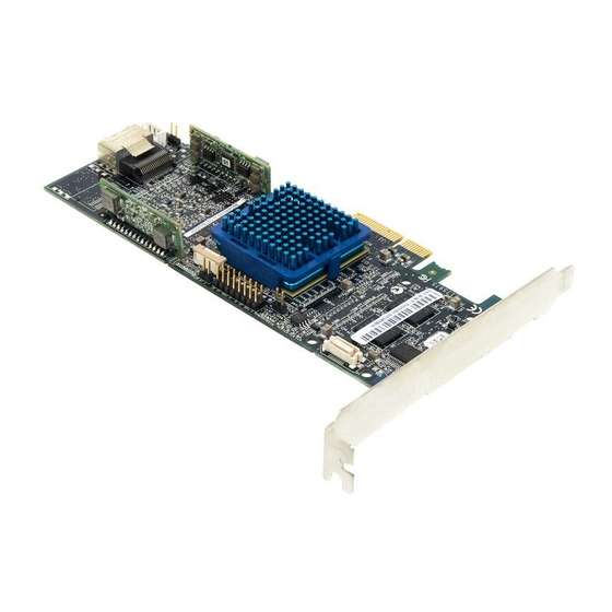
Page 19: About The Icp5045Bl
About the ICP5045BL The ICP5045BL is a SAS RAID controller with these features: Aggregate Activity LED header for CN0 Battery connector Mounting bracket Form Factor Bus compatibility PCIe bus width PCIe bus speed PHYs Standard cache Connectors, internal RAID levels... -
Page 20: About The Icp5085Bl
256 MB DDR2 Two SAS x4 (SFF-8087) 0, 1, 1E, 10, 5, 5EE, 50,6, 60, JBOD SATA, SATA II, SAS 8 (or up to 100 with expanders) I2C and SGPIO Adaptec Battery Module 800 (sold separately—see page ● 2 internal SAS connectors... -
Page 21: About The Icp5125Br
256 MB DDR2 Three SAS x4 (SFF-8087) 0, 1, 1E, 10, 5, 5EE, 50,6, 60, JBOD SATA, SATA II, SAS 12 (or up to 100 with expanders) I2C and SGPIO Adaptec Battery Module 800 (sold separately—see page ● 3 internal SAS connectors... -
Page 22: About The Icp5165Br
256 MB DDR2 Four SAS x4 (SFF-8087) 0, 1, 1E, 10, 5, 5EE, 50,6, 60, JBOD SATA, SATA II, SAS 16 (or up to 100 with expanders) I2C and SGPIO Adaptec Battery Module 800 (sold separately—see page ● 4 internal SAS connectors... -
Page 23: About The Icp9085Li
SES2 Yes with these specifications: 3.0 V, 90.0 mA. The internal speaker is not required, as the onboard speaker volume is appropriate for most environments. Adaptec Battery Module 600 (sold separately—see ● Charge LED (for battery backup module) Alarm connector... -
Page 24: About The Icp5085Br
SES2 Yes with these specifications: 3.0 V, 90.0 mA. The internal speaker is not required, as the onboard speaker volume is appropriate for most environments. Adaptec Battery Module 600 (sold separately—see ● Charge LED (for battery backup module) Alarm connector... -
Page 25: About The Icp9047Ma
256 MB 4x SATA connector 0, 1, 1E, 5, 5EE, 6, 10 Up to 4 Serial ATA/Serial ATA II disk drives, 48-bit LBA supports drives larger than 137GB Adaptec Battery Module 500 (sold separately—see ● Activity LED connector Battery connector... -
Page 26: About The Icp9087Ma
8x SATA connector 0, 1, 1E, 5, 5EE, 6, 10, 50, 60 Up to 8 Serial ATA/Serial ATA II disk drives, 48-bit LBA supports drives larger than 137GB Adaptec Battery Module 500 (sold separately—see ● Activity LED connector Battery connector... -
Page 27: About The Icp9014Ro
PCI-X, 3.3 V 64-bit 133 MHz 256 MB Internal = One 68-pin high-density External = One 68-pin VHDCI 0, 1, 1E, 5, 5EE, 6, 10, 50, 60 Up to 15 SCSI devices SAFTE Adaptec Battery Module 400 (sold separately—see ● page... -
Page 28: About The Icp9024Ro
64-bit 133 MHz 256 MB Internal = Two 68-pin high-density External = Two 68-pin VHDCI 0, 1, 1E, 5, 5EE, 6, 10, 50, 60 Up to 30 SCSI devices SAFTE Adaptec Battery Module 400 (sold separately—see ● Activity LED page... -
Page 29: Getting Started
Getting Started In this chapter... Choosing a RAID Level... 30 Selecting Disk Drives... 31 Selecting Cables ... 32 Installation Options ... 34 Basic Installation Steps... 34 This chapter provides the basic information you need to set up your disk drives and arrays the way you want them. -
Page 30: Choosing A Raid Level
Choosing a RAID Level This section provides a brief overview of the RAID levels supported by your ICP RAID controller, including the minimum and maximum number of disk drives required by each. RAID 0 (Non-redundant Array)—Stripes data across multiple disk drives. Improved ●... -
Page 31: Selecting Disk Drives
Selecting Disk Drives When selecting disk drives for your RAID array, ensure that all the disk drives have the same performance level. You can use different-sized disk drives in the array, but the array will be limited to the capacity of the smallest and slowest disk drive. For more information, refer to the ICP Storage Manager User’s Guide or online Help. -
Page 32: Selecting Cables
Selecting Cables This section describes the cable options and requirements for your ICP controller: For SAS cables, see this page. ● SATA cables, see page ● SCSI cables, see page ● SAS Cables You need one SAS cable for each disk drive you are connecting to your ICP SAS RAID controller. -
Page 33: Sata Cables
External SAS (SFF-8088)—Connects to SAS or SATA disk drives on a backplane. Internal SAS (SFF-8484)—Connects to SAS or SATA disk drives on a backplane. Internal mini-SAS (SFF-8087)—Connects to SAS or SATA disk drives on a backplane. or the Adaptec Web site at ●... -
Page 34: Scsi Cables
Adaptec Web site at Internal SCSI cable—Connects to up to seven internal SCSI disk drives and devices. External SCSI cable—Connects to an external SCSI disk drive or device. or the Adaptec Web site at www.adaptec.com. page 43). ● page... -
Page 35: Installing On An Existing Operating System
Create a bootable array (see page Install your operating system and the controller driver (see Install ICP Storage Manager and begin to manage your data storage (see Note: Currently, ICP Storage Manager is not supported on FreeBSD. To create and manage ICP RAID Configuration arrays, use the Installing on an Existing Operating System... -
Page 36: Installing The Controller And Disk Drives
Installing the Controller and Disk Drives In this chapter... Before You Begin ... 37 Installing the Controller... 37 Connecting Disk Drives to SAS RAID Controllers... 38 Connecting Disk Drives to SATA RAID Controllers ... 40 Connecting Disk Drives to SCSI RAID Controllers ... 40 Connecting External Devices... -
Page 37: Before You Begin
Before You Begin Read Safety Information on page ● Familiarize yourself with your ICP RAID controller’s physical features and the RAID levels ● that it supports (see Ensure you have the right quantity of disk drives for the RAID level you want to use for ●... -
Page 38: Connecting Disk Drives To Sas Raid Controllers
For SAS RAID controllers, see ● For SATA RAID controllers, see ● For SCSI RAID controllers, see ● If you are not installing internal disk drives, close your computer cabinet, reattach the power cord, then continue with Connecting Disk Drives to SAS RAID Controllers You can connect SAS disk drives, SATA disk drives, or a combination of both to your SAS RAID controller. -
Page 39: Connecting To A System Backplane
Chapter 5: Installing the Controller and Disk Drives Use internal SAS or mini-SAS cables to attach the disk drives to the controller. 4-wide internal SAS connector External SAS connector External SAS cable 4-wide internal SAS connectors SAS to SATA fan-out cable When all internal disk drives have been installed and attached to the controller, close your computer cabinet, reattach the power cord, then continue with Devices on page... -
Page 40: Connecting Disk Drives To Sata Raid Controllers
External SAS cable connecting to a drive bay When all internal disk drives have been installed and connected, close your computer cabinet, reattach the power cord, then continue with Connecting Disk Drives to SATA RAID Controllers Install your SATA disk drives, following the instructions in your system’s documentation. There are no jumpers or switches to set on the SATA controller or disk drives. -
Page 41: Connecting External Devices
Controller Device State Failed Rebuilding Blink Other Chapter 5: Installing the Controller and Disk Drives page or the Adaptec Web site at www.adaptec.com. Backplane Connections on page Slot State LED Flash State Device is faulty Device is rebuilding Slow flash... -
Page 42: Creating A Bootable Array
Creating a Bootable Array In this chapter... Setting the Boot Controller... 43 Creating an Array ... 43 Making Your Array Bootable ... 46 This chapter explains how to set your ICP controller to be the boot controller, and how to create a bootable array. -
Page 43: Setting The Boot Controller
Setting the Boot Controller Note: If your system won’t contain more than one bootable controller, skip to the next section, Creating an Array. Your ICP RAID controller supports bootable disk drives and bootable arrays. To enable your system to boot from either a disk drive or an array connected to your controller: Enter the system setup. - Page 44 Select Initialize Drives, then press Enter. Select at least three disk drives for the array, press Insert for each selected disk drive, then press Enter. Caution: During initialization, all data is deleted from the disk. Before continuing, back up any data you want to keep. Press Y, then press Enter.
-
Page 45: Creating An Array With Icp Storage Manager
Creating an Array with ICP Storage Manager This section describes how to use the ICP Storage Manager configuration wizard to build a RAID 5 array. Note: You will need the ICP Storage Manager Installation CD to complete this task. To create a RAID 5 array: Insert the ICP Storage Manager Installation CD into your CD drive, then restart your computer. -
Page 46: Making Your Array Bootable
Review the information that is displayed. Note: In DAS environments, ICP Storage Manager uses the term logical drives when referring to arrays (see In this example, ICP Storage Manager has used thirteen equal-sized disk drives to automatically create one logical drive with RAID 5 and a hot spare. To exclude specific disk drives from the logical drive, specify a size for the logical drive, or to make other changes to the configuration, click Modify logical devices. -
Page 47: Installing The Driver And An Operating System
Installing the Driver and an Operating System In this chapter... Before You Begin ... 48 Creating a Driver Disk ... 48 Installing with Windows ... 49 Installing with Red Hat Linux ... 49 Installing with SUSE Linux... 50 Installing with NetWare ... 50 Installing with OpenServer ... -
Page 48: Before You Begin
Before You Begin Install and connect your ICP RAID controller and internal disk drives (see ● Create a bootable array (see ● Create a driver disk (see the following section). ● Note: For up-to-date operating system version support, visit the ICP Web Site at vortex.com. -
Page 49: Installing With Windows
For VMware, see ● For FreeBSD, see ● Installing with Windows Note: You will need your Windows Installation CD to complete this task. To install the ICP RAID controller driver while installing Windows: Insert your Windows CD, then restart the computer. Follow the on-screen instructions to begin the Windows installation. -
Page 50: Installing With Suse Linux
Installing with SUSE Linux To install the ICP RAID controller driver while installing SUSE Linux: Insert the first SUSE Installation CD. Restart your computer. When the SUSE installation selection screen appears, choose the type of installation you want, then press the F6 key to indicate the use of a driver disk. (If F6 is not shown on the screen, you may have an older version of SUSE;... -
Page 51: Installing With Openserver
From the lower window menu, select Continue, then press Enter. If the driver installation process fails, the server console is displayed so you can see the cause of the failure. To modify disk partitions, apply hot fixes, or perform volume maintenance, refer to your NetWare documentation. -
Page 52: Installing With Unixware
Installing with UnixWare Note: You will need your UnixWare Installation CD to complete this task. To install the driver when installing UnixWare: Insert the UnixWare Installation CD. Restart your computer. Follow the on-screen instructions to begin the UnixWare installation. When prompted to load more HBA drivers, insert the driver disk, then select Yes. (To load more HBA drivers, repeat this step.) When all drivers have loaded, select No. -
Page 53: Installing With Freebsd
Installing with FreeBSD Note: You will need your FreeBSD Installation CD to complete this task. To install the driver when installing FreeBSD: Insert the FreeBSD Installation CD. Restart your computer. When the FreeBSD start screen opens, select 6 to escape to loader prompt. Type load kernel Insert the driver floppy disk. -
Page 54: Installing The Driver On An Existing Operating System
Installing the Driver on an Existing Operating System In this chapter... Before You Begin ... 55 Creating a Driver Disk ... 55 Installing on Windows ... 56 Installing on Red Hat or SUSE Linux... 56 Installing on NetWare ... 56 Installing on OpenServer ... -
Page 55: Before You Begin
Chapter 8: Installing the Driver on an Existing Operating System Before You Begin Before you begin, install and connect your ICP RAID controller and internal disk drives (see page 36). You must also create a driver disk (see Note: For up-to-date operating system version support, visit the ICP Web Site at vortex.com. -
Page 56: Installing On Windows
Chapter 8: Installing the Driver on an Existing Operating System For FreeBSD, see ● Installing on Windows To install the driver on Windows: Start or restart Windows. The Found New Hardware Wizard opens and searches for the driver. Insert the driver disk, select Floppy drive, then click Next. Click Next, then click Next again. -
Page 57: Installing On Openserver
Chapter 8: Installing the Driver on an Existing Operating System If aacraid.ham has already been detected, delete it. At the Driver Name menu, press the Insert key. Insert the driver disk, press the Insert key, then press F3. At the A:\ prompt, press Enter. The driver installs. -
Page 58: Installing On Unixware
To install the driver on VMware: Start your computer, then insert the driver disk. At the console screen of the VMware server, mount the Adaptec CD: mount –r /dev/cdrom /mnt/cdrom. Install the module RPM: rpm –ivh /mnt/cdrom/xxx/yyy.rpm... -
Page 59: Installing On Freebsd
Chapter 8: Installing the Driver on an Existing Operating System Installing on FreeBSD To install the driver on FreeBSD: Start your computer. Insert and mount the driver disk: mount -t msdos /dev/fd0 /mnt Copy the driver package to the /tmp directory: cp /mnt/aac-02.00.00-x.tgz /tmp Install the driver package: pkg_add /tmp/aac-02.00.00-x.tgz... -
Page 60: Managing Your Storage Space
Managing Your Storage Space In this chapter... About ICP Storage Manager ... 61 About the Adaptec RAID Controller Configuration Utility ... 61 About the ICP RAID Configuration Utility... 62 About the ICP Flash Utility ... 62 Which Utility Should I Use? ... 62 Once you have installed your ICP RAID controller, disk drives (or other devices), and device driver, you can begin to build and manage your storage space. -
Page 61: About Icp Storage Manager
ICP Storage Manager User’s Guide , also included on the ICP Storage Manager Installation CD. About the Adaptec RAID Controller Configuration Utility The Adaptec RAID Controller Configuration (ARCCONF) is a command line utility that you can use to perform some basic array and configuration management functions. With ARCCONF, you can: Create and delete logical drives ●... -
Page 62: About The Icp Raid Configuration Utility
About the ICP RAID Configuration Utility The ICP RAID Configuration utility is a BIOS-based utility that you can use to create and manage controllers, disk drives and other devices, and arrays. The ICP RAID Configuration utility comprises these tools: Array Configuration Utility (ACU)—For creating and managing arrays, and initializing ●... -
Page 63: Solving Problems
Solving Problems In this chapter... Troubleshooting Checklist ... 64 Silencing the Alarm ... 64 Recovering from a Disk Drive Failure ... 64 Resetting the Controller... 66 This chapter provides basic troubleshooting information and solutions for solving controller problems. -
Page 64: Troubleshooting Checklist
If you are still unable to resolve a problem, you can find additional troubleshooting information and direction on the ICP Web site at Knowledgebase at ask.adaptec.com. Silencing the Alarm If your ICP RAID controller includes an alarm, the alarm will sound when an error occurs. To... -
Page 65: Failed Disk Drive Protected By A Hot Spare
Failed Disk Drive Protected by a Hot Spare When an array is protected by a hot spare, if a disk drive in that array fails the hot spare is automatically incorporated into the array and takes over for the failed drive. To recover from the failure: Remove and replace the failed disk drive (following manufacturer’s instructions). -
Page 66: Multiple Failures In The Same Array
Multiple Failures in the Same Array Except in RAID 6 and RAID 60 arrays (see same time in the same array, the data can’t be recovered. Correct the cause of the failure or replace the failed disk drives. Then, restore your data (if available). -
Page 67: Introduction To Serial Attached Scsi
Introduction to Serial Attached SCSI In this appendix... Terminology Used in This Chapter ... 68 What is SAS? ... 68 How Do SAS Devices Communicate? ... 69 What’s a Phy? ... 69 What’s a SAS Port?... 70 What’s a SAS Address?... 70 What’s a SAS Connector? ... -
Page 68: Terminology Used In This Chapter
Terminology Used in This Chapter For convenience, SAS HBAs and SAS RAID controllers are referred to generically in this chapter as SAS cards. HBAs, RAID controllers, disk drives, and external disk drive enclosures are referred to as end devices and expanders are referred to as expander devices. For convenience, this chapter refers to end devices and expander devices collectively as SAS devices. -
Page 69: How Do Sas Devices Communicate
How Do SAS Devices Communicate? SAS devices communicate with each other through links. A link is a physical connection between two phys. As shown in the following figure, SAS devices contain ports (see and each phy contains one transmitter and one receiver—one transceiver. A phy can belong to one port only. -
Page 70: What's A Sas Port
What’s a SAS Port? Note: Because the physical link between SAS devices is from phy to phy, rather than port to port, a “port” is more of a virtual concept, different from what is normally considered a port on other types of RAID controllers and storage devices. A port is one or more phys. -
Page 71: How Are Disk Drives Identified In Sas
The number of end devices is limited to the number of slots available on the backplane. For example, the Adaptec S50 enclosure, which contains an expander, is a backplane connection that supports up to 12 SAS or SATA disk drives. -
Page 72: Sas Expander Connections
Appendix A: Introduction to Serial Attached SCSI Some backplanes support daisy-chain expansion to other backplanes. For example, you can daisy-chain (connect one to the next) up to nine Adaptec S50 enclosures to a single SAS card in a host system. -
Page 73: How Is Sas Different From Parallel Scsi
How is SAS Different from Parallel SCSI? In summary, although SAS and parallel SCSI both use the SCSI command set, how they move data from one place to another is very different. To support point-to-point serial data transport, SAS introduces new types of connectors, cables, connection options, and terminology. -
Page 74: Understanding Raid
Understanding RAID In this appendix... Understanding Drive Segments... 75 Non-redundant Arrays (RAID 0) ... 75 RAID 1 Arrays ... 76 RAID 1 Enhanced Arrays... 76 RAID 10 Arrays ... 77 RAID 5 Arrays ... 78 RAID 5EE Arrays... 79 RAID 50 Arrays ... 80 RAID 6 Arrays ... -
Page 75: Understanding Drive Segments
Understanding Drive Segments A drive segment is a disk drive or portion of a disk drive that is used to create an array. A disk drive can include both RAID segments (segments that are part of an array) and available segments. -
Page 76: Raid 1 Arrays
RAID 1 Arrays A RAID 1 array is built from two disk drives, where one disk drive is a mirror of the other (the same data is stored on each disk drive). Compared to independent disk drives, RAID 1 arrays provide improved performance, with twice the read rate and an equal write rate of single disks. -
Page 77: Raid 10 Arrays
RAID 10 Arrays A RAID 10 array is built from two or more equal-sized RAID 1 arrays. Data in a RAID 10 array is both striped and mirrored. Mirroring provides data protection, and striping improves performance. Drive segment size is limited to the size of the smallest disk drive in the array. For instance, an array with two 250 GB disk drives and two 400 GB disk drives can create two mirrored drive segments of 250 GB, for a total of 500 GB for the array, as shown in this figure. -
Page 78: Raid 5 Arrays
RAID 5 Arrays A RAID 5 array is built from a minimum of three disk drives, and uses data striping and parity data to provide redundancy. Parity data provides data protection, and striping improves performance. Parity data is an error-correcting redundancy that’s used to re-create data if a disk drive fails. In RAID 5 arrays, parity data (represented by Ps in the next figure) is striped evenly across the disk drives with the stored data. -
Page 79: Raid 5Ee Arrays
RAID 5EE Arrays A RAID 5EE array—also known as a hot space—is similar to a RAID 5 array except that it includes a distributed spare drive and must be built from a minimum of four disk drives. Unlike a hot spare, a distributed spare is striped evenly across the disk drives with the stored data and parity data, and can’t be shared with other logical disk drives. -
Page 80: Raid 50 Arrays
RAID 50 Arrays A RAID 50 array is built from six to forty-eight disk drives configured as two or more RAID 5 arrays, and stripes stored data and parity data across all disk drives in both RAID 5 arrays. (For more information, see RAID 5 Arrays on page Note:... -
Page 81: Raid 6 Arrays
RAID 6 Arrays A RAID 6 array—also known as dual drive failure protection—is similar to a RAID 5 array because it uses data striping and parity data to provide redundancy. However, RAID 6 arrays include two independent sets of parity data instead of one. Both sets of parity data are striped separately across all disk drives in the array. -
Page 82: Selecting The Best Raid Level
Selecting the Best RAID Level Use this table to select the RAID levels that are most appropriate for the logical drives on your storage space, based on the number of available disk drives and your requirements for performance and reliability. RAID Level Redundancy RAID 0... -
Page 83: Using The Icp Raid Configuration Utility
Using the ICP RAID Configuration Utility In this appendix... Introduction to the ICP RAID Configuration Utility ... 84 Running the ICP RAID Configuration Utility... 84 Using the ACU to Create and Manage Arrays ... 84 Using the -Select Utility to Modify Controller Settings ... 86 Formatting and Verifying Disk Drives ... -
Page 84: Introduction To The Icp Raid Configuration Utility
Introduction to the ICP RAID Configuration Utility The ICP RAID Configuration utility comprises these tools: The Array Configuration Utility (ACU)—For creating and managing arrays, and ● initializing and rescanning disk drives (see Note: Also available—ACU for DOS. See A -Select Utility—SerialSelect, SATASelect, or SCSISelect, for modifying your controller ●... -
Page 85: Managing Existing Arrays
Appendix C: Using the ICP RAID Configuration Utility Managing Existing Arrays To view or modify existing arrays, select Manage Arrays from the main ACU menu. From the Manage Arrays menu, you can: View the properties of an array. ● Note: Failed drives are displayed in a different text color. -
Page 86: Secure Erasing Disk Drives
Secure Erasing Disk Drives When you perform a secure erase on a disk drive, all data on that disk drive is completely and irretrievably eradicated. Secure erase performs three distinct writing passes to the disk drive being erased—it does not just write zeros. Performing a secure erase takes up to six times longer than clearing (or zeroing) a disk drive. -
Page 87: Modifying Your Controller's Configuration
Appendix C: Using the ICP RAID Configuration Utility Modifying Your Controller’s Configuration Note: Default controller settings are suitable for most computers. ICP recommends that you do not change the default setting. To modify your controller’s settings, select Controller Configuration from the main -Select utility menu. -
Page 88: Sas-Specific Controller Settings
Appendix C: Using the ICP RAID Configuration Utility SAS-specific Controller Settings In addition to the general settings listed on settings that can be modified if required. (For more information about SAS, see Note: This feature is not available with the ICP5125BR or ICP5165BR controllers. To modify SAS-specific settings, select PHY Configuration from the SerialSelect main menu. -
Page 89: Scsi-Specific Controller Settings
Appendix C: Using the ICP RAID Configuration Utility SCSI-specific Controller Settings In addition to the general settings listed on settings that can be modified if required. To modify SCSI-specific settings, select SCSI Configuration from the SCSISelect main menu. SCSI Device Settings You can use SCSISelect to modify some of the settings on the SCSI devices connected to your SCSI controller. -
Page 90: Formatting And Verifying Disk Drives
Formatting and Verifying Disk Drives You can use the disk utilities to low-level format or verify your disk drives. (New disk drives are low-level formatted at the factory and do not need to be low-level formatted again.) Caution: Before you format a disk drive, back up all data. Formatting destroys all data on a disk drive. -
Page 91: Viewing The Event Log
The location information of a disk drive is determined by three types of connections: Direct attached drives ● for example CN1 (connector 1) is connected to DEV1 (device 1). For more information, see Direct-attach Connections Storage Enclosure Processor (SEP) managed devices ●... -
Page 92: Using The Array Configuration Utility For Dos
Using the Array Configuration Utility for DOS In this appendix... Getting Started ... 93 Working in the ACU Using Menus... 93 Running the ACU Using Scripts... 94 This chapter describes the Array Configuration Utility (ACU) for DOS, a text-based utility that you can use to create, configure, and manage arrays. -
Page 93: Getting Started
Getting Started Note: You need a bootable floppy disk to complete this task. The ACU for DOS runs from a floppy disk which you can create using the RAID Installation CD that came in your ICP RAID controller kit. To create the ACU floppy disk: Insert your RAID Installation CD into the CD drive, then browse to this file: packages/firmware/controllermodel/acu.exe Where controllermodel is the model number of your ICP RAID controller. -
Page 94: Running The Acu Using Scripts
Running the ACU Using Scripts To work in the ACU using scripts: Insert the ACU floppy disk (see The computer boots to the DOS command line. Type on the command line, specify a script file, and specify either the /P or /R switches listed in the following table. -
Page 95: About Record Mode
Appendix D: Using the Array Configuration Utility for DOS About Record Mode Note: You can also create a script file manually (see the following section). In Record Mode, the ACU writes a RAID controller’s existing array configuration to a specified script file, which lets you create the same configuration by running the ACU in Playback Mode (/P switch) with the resulting script. -
Page 96: Array Definition Block Keywords
Appendix D: Using the Array Configuration Utility for DOS Array Definition Block Keywords The array definition block always begins with the keyword Array and ends with the keyword End. The other required array definition keywords are Drives and Type. Array definition keywords and descriptions are listed in this table. Keyword Required? Description Array... - Page 97 Appendix D: Using the Array Configuration Utility for DOS End Keyword End is a required keyword, indicating the end of the block. HotspareDrives Keyword Hotspare Drives is an optional keyword, specifying the hot spares to assign to the array. The syntax for listing hot spares is the same as the not specified, no hot spares are assigned to the array.
- Page 98 Appendix D: Using the Array Configuration Utility for DOS Method Keyword Method is an optional keyword, indicating which method to use when creating a redundant (RAID 1, 1E, 10, 5, 5EE, 50, 6 and 60) array. Possible values: Build (the default)—Perform a Build/Verify process on the array. Takes longer than Clear, ●...
-
Page 99: Channel Definition Block Keywords-Scsi Only
Appendix D: Using the Array Configuration Utility for DOS Type Keyword Type is a required keyword, indicating the array type. There is no default value. The possible values: Volume, RAID0, RAID1, RAID5, RAID10, or RAID50. Depending on the RAID levels supported by your RAID controller, additional possible values are: RAID1E, RAID5EE, RAID6, RAID60. -
Page 100: Acu Error Codes
Appendix D: Using the Array Configuration Utility for DOS ControllerID Keyword ControllerID is an optional keyword to change the SCSI ID of the controller. Normally, the SCSI controller is assigned SCSI ID 7 on each of its channels. You can specify any ID value between 0 and 7. -
Page 101: Sample Scripts
Appendix D: Using the Array Configuration Utility for DOS Code Description Unable to read SATA port parameters. Unable to read SCSI channel parameters. Unable to write SATA port parameters. Unable to write SCSI channel parameters. Failed in getting kernel version. Unknown product ID. Kernel timeout in writing command. - Page 102 Appendix D: Using the Array Configuration Utility for DOS # Clear the array (don’t build/verify it) Method=Clear # Don’t wait for clear to complete Wait=No # Use drives 0, 1, 2 Drives=0:0:0, 0:1:0, 0:2:0 Sample Script for SATA Controllers This is a sample ACU file that will initialize all disk drives connected to the SATA controller and create a RAID 5 array with the disk drives on ports 0, 1, and 2.
-
Page 103: Using The Icp Flash Utility
Using the ICP Flash Utility In this appendix... System Requirements ... 104 Before You Begin ... 104 Running the Menu-based IFU... 105 Running the IFU from the Command Line... 106 Updating the Flash Using the IFU Command Line... 109 This chapter describes how to use theICP Flash Utility (IFU), a text-based DOS utility that you can use to update, save, or verify the RAID controller’s firmware BIOS and NVRAM. -
Page 104: System Requirements
System Requirements MS–DOS version 5.0 or later. ● Note: You can’t run the IFU from a DOS command prompt window under any version of Windows. At least 8 MB of extended memory. ● Compatibility Notes Supports HIMEM.SYS; compatible with other DOS drivers running under HIMEM.SYS ●... -
Page 105: Creating The Firmware Floppy Disks
Creating the Firmware Floppy Disks Note: You will need at least two bootable MS-DOS floppy disks to complete this task. You can’t create a bootable floppy disk using Windows 2000. To create the firmware floppy disks: Create a bootable MS–DOS floppy disk and copy these files to it: IFU.exe ●... -
Page 106: Running The Ifu From The Command Line
Complete the flash operation and restart your computer before trying to use the RAID controller again. (You can not use your RAID controller while you are updating its flash.) Running the IFU from the Command Line Note: You can also run a menu-based IFU (see To run the IFU from the command line: Power off your computer, insert the first IFU floppy disk, then power on your computer. - Page 107 These switches are available: /C <Controller ID>—One or more RAID controller IDs representing the set of RAID ● controllers on which to perform the specified command. The default is 0; if the computer has multiple RAID controllers, the IFU defaults to controller 0 unless you specify otherwise.
- Page 108 Verify Compares the contents of each of the flash components on a RAID controller to the corresponding image in a UFI file, and indicates whether they match. After using the VERIFY command, you must restart the computer. The command syntax for the VERIFY command is as follows: IFU VERIFY [/C<Controller ID>] [/D <UFI File Path>] This example shows a typical system response after a VERIFY command.
-
Page 109: Updating The Flash Using The Ifu Command Line
Updating the Flash Using the IFU Command Line Create the firmware floppy disks (see Power off your computer, insert the first IFU floppy disk, then power on your computer. If your computer isn’t set up to boot from the bootable floppy disk, enter the system setup utility to change the setting. -
Page 110: Icp Serial Controller Led And I2C Connector Reference
ICP9047MA Activity LED and I2C Connector Specification ... 111 ICP9087MA Activity LED and I2C Connector Specification ... 112 ICP5805BL LED and I2C Connector Specification... 113 ICP5045BL LED and I2C Connector Specification... 113 ICP5085BL LED and I2C Connector Specification... 115 ICP5125BR LED and I2C Connector Specification ... 117 ICP5165BR LED and I2C Connector Specification ... -
Page 111: Icp9047Ma Activity Led And I2C Connector Specification
Appendix F: ICP Serial Controller LED and I2C Connector Reference ICP9047MA Activity LED and I2C Connector Specification 2199900-R ICP9047MA LED Board Connector: Molex 53398-0490 or equivalent ● LED Mating Cable Connector: Molex 51021-0400 or equivalent ● J11: Pin Number Note: Board circuitry supports COMMON ANODE backplane implementations ICP9047MA Activity LED Board Connector: Molex 22-28-8022 2.54mm 1x2 RA Header ●... -
Page 112: Icp9087Ma Activity Led And I2C Connector Specification
Appendix F: ICP Serial Controller LED and I2C Connector Reference ICP9087MA Activity LED and I2C Connector Specification 2200000-R ICP9087MA LED Board Connector #1: Molex 53398-0490 or equivalent ● LED Mating Cable Connector #1: Molex 51021-0400 or equivalent ● J11: Pin Number Note: Board circuitry supports COMMON ANODE backplane implementations ICP9087MA LED Board Connector #2: Molex 53398-0490 or equivalent... -
Page 113: Icp5805Bl Led And I2C Connector Specification
ACT0_7_LED_L (5) +3.3V ACT0_7_LED_L (6) +3.3V ACT0_7_LED_L (7) ICP5045BL LED and I2C Connector Specification 2250900-R ICP5045BL LED Board Connector: Molex 10-89-7162 2.54mm 2x8 Header or equivalent. ● LED Mating Cable Connector: Molex 22-55-2081 or equivalent. ● Signal Description IIC_EM_DATA I2C Data... - Page 114 +3.3V ACT0_7_LED_L (7) +3.3V ACT0_7_LED_L (6) +3.3V ACT0_7_LED_L (5) +3.3V ACT0_7_LED_L (4) ICP5045BL Aggregate Activity LED Board Connector: Molex 22-28-8022 2.54mm 1x2 RA ● Header or equivalent. LED Mating Cable Connector: Molex 50-57-9002 or equivalent. ● J12: Pin Number Signal AGGREGATE4_7_L +3.3V...
-
Page 115: Icp5085Bl Led And I2C Connector Specification
Appendix F: ICP Serial Controller LED and I2C Connector Reference Pin Number Signal CONTROLLER_TYPEB_BUF BACKPLANE_TYPEB ICP5085BL LED and I2C Connector Specification 2251100-R ICP5085BL LED Board Connector: Molex 10-89-7162 2.54mm 2x8 Header or equivalent ● LED Mating Cable Connector: Molex 22-55-2161 or equivalent ●... - Page 116 Appendix F: ICP Serial Controller LED and I2C Connector Reference LED Mating Cable Connector: Molex 50-57-9002 or equivalent ● J12: Pin Number Signal AGGREGATE4_7_L +3.3V ICP5085BL I2C Board Connector: Molex 22-43-6030 or equivalent ● I2C Mating Cable Connector: Molex 22-43-3030 or equivalent ●...
-
Page 117: Icp5125Br Led And I2C Connector Specification
Appendix F: ICP Serial Controller LED and I2C Connector Reference SFF-8087 Connector J5: Pin Number Signal SB0_CONB SB1_CONB SB4_CONB SB5_CONB CONTROLLER_TYPEB_BUF BACKPLANE_TYPEB ICP5125BR LED and I2C Connector Specification 2251300-R ICP5125BR LED Board Connector: Molex 10-89-7162 2.54mm 2x8 Header or equivalent ●... - Page 118 Appendix F: ICP Serial Controller LED and I2C Connector Reference J17: Pin Number Signal +3.3V ACT8_15_LED_L (0) +3.3V ACT8_15_LED_L (1) +3.3V ACT8_15_LED_L (2) +3.3V ACT8_15_LED_L (3) ICP5125BR Aggregate Activity LED Board Connector: Molex 22-28-8022 2.54mm 1x2 ● RA Header or equivalent LED Mating Cable Connector: Molex 50-57-9002 or equivalent ●...
- Page 119 Appendix F: ICP Serial Controller LED and I2C Connector Reference The following pins are tied to Sideband Signals of SFF-8087 connector J3 (Ports 0-3) Pin Number Signal SDA_A SCL_A ICP5125BR I2C Board Connector: Molex 22-43-6030 or equivalent ● I2C Mating Cable Connector: Molex 22-43-3030 or equivalent ●...
-
Page 120: Icp5165Br Led And I2C Connector Specification
Appendix F: ICP Serial Controller LED and I2C Connector Reference SFF-8087 Connector J5: Pin Number Signal SB0_CONB SB1_CONB SB4_CONB SB5_CONB CONTROLLER_TYPEB_BUF BACKPLANE_TYPEB SFF-8087 Connector J18: Pin Number Signal SB0_CONC SB1_CONC SB4_CONC SB5_CONC CONTROLLER_TYPEC_BUF BACKPLANE_TYPEC ICP5165BR LED and I2C Connector Specification 2251500-R ICP5165BR LED Board Connector: Molex 10-89-7162 2.54mm 2x8 Header or equivalent ●... - Page 121 Appendix F: ICP Serial Controller LED and I2C Connector Reference Board Pin Number Signal ACT0_7_LED_L (4) +3.3V ACT0_7_LED_L (5) +3.3V ACT0_7_LED_L (6) +3.3V ACT0_7_LED_L (7) ICP5165BR LED Board Connector: Molex 10-89-7162 2.54mm 2x8 Header or equivalent ● LED Mating Cable Connector: Molex 22-55-2161 or equivalent ●...
- Page 122 Appendix F: ICP Serial Controller LED and I2C Connector Reference LED Mating Cable Connector: Molex 50-57-9002 or equivalent ● J12: Pin Number Signal AGGREGATE4_7_L +3.3V ICP5165BR Aggregate Activity LED Board Connector: Molex 22-28-8022 2.54mm 1x2 ● RA Header or equivalent LED Mating Cable Connector: Molex 50-57-9002 or equivalent ●...
- Page 123 Appendix F: ICP Serial Controller LED and I2C Connector Reference ICP5165BR I2C Board Connector: Molex 22-43-6030 or equivalent ● I2C Mating Cable Connector: Molex 22-43-3030 or equivalent ● J19: The following pins are tied to Sideband Signals of SFF-8087 connector J18 (Ports 0-3) Pin Number Signal SDA_C...
-
Page 124: Icp9085Li Led And I2C Connector Specification
Appendix F: ICP Serial Controller LED and I2C Connector Reference Pin Number Signal CONTROLLER_TYPEB_BUF BACKPLANE_TYPEB SFF-8087 Connector J18: Pin Number Signal SB0_CONC SB1_CONC SB4_CONC SB5_CONC CONTROLLER_TYPEC_BUF BACKPLANE_TYPEC SFF-8087 Connector J14: Pin Number Signal SB0_COND SB1_COND SB4_COND SB5_COND CONTROLLER_TYPED_BUF BACKPLANE_TYPED ICP9085LI LED and I2C Connector Specification 2216800-R ICP9085LI RoHS KIT ICP9085LI Activity LED Board Connector: Molex 10-89-7102 2.54mm 2x5 Header or... -
Page 125: Icp5085Br Led And I2C Connector Specification
Appendix F: ICP Serial Controller LED and I2C Connector Reference J10: J10 Pin Number Signal XDEVLED0- XDEVLED1- XDEVLED2- XDEVLED3- XDEVLED4- XDEVLED5- XDEVLED6- XDEVLED7- AGGREGATE_L +3_3V_ACT Note: Board circuitry supports COMMON ANODE backplane implementations ICP9085LI I2C Board Connector: There is NO separate I2C connector. I2C signals are ●... - Page 126 Appendix F: ICP Serial Controller LED and I2C Connector Reference LED Mating Cable Connector: Molex 22-552101 or equivalent ● J10: J10 Pin Number Signal XDEVLED0- XDEVLED1- XDEVLED2- XDEVLED3- XDEVLED4- XDEVLED5- XDEVLED6- XDEVLED7- AGGREGATE_L +3_3V_ACT Note: Board circuitry supports COMMON ANODE backplane implementations ICP5085BR I2C Board Connector: There is NO separate I2C connector.
-
Page 127: Safety Information
Safety Information To ensure your personal safety and the safety of your equipment: Keep your work area and the computer clean and clear of debris. ● Before opening the system cabinet, unplug the power cord. ● Electrostatic Discharge (ESD) Caution: ESD can damage electronic components when they are improperly handled, and can result in total or intermittent failures. -
Page 128: Technical Specifications
Technical Specifications In this appendix... Environmental Specifications... 129 DC Power Requirements... 129 Current Requirements... 129... -
Page 129: Environmental Specifications
Altitude Note: Forced airflow is recommended. DC Power Requirements Bus Type PCI, PCI-X, PCIe PCI, PCI-X PCIe Current Requirements ICP Model ICP5805BL ICP5045BL ICP5085BL ICP5125BR ICP5165BR ICP9085LI ICP5085BR ICP9047MA ICP9087MA ICP9014RO ICP9024RO Appendix H: Technical Specifications 0 °C to 40 ° C 0 °C to 55 °... - Page 130 Adaptec RAID Controller Configuration utility. See ARCCONF adapters. See controllers advanced data protection Alarm Control setting ARCCONF Array Background Consistency Check setting Array Configuration Utility. See ACU...
- Page 131 command line utility connectors contents of controller kit Controller SCSI Channel ID setting Controller SCSI Channel Termination setting controllers Alarm Control setting Array Background Consistency Check setting Array-based BBS Support setting array-level features Automatic Failover setting BBS Support setting cables CD-ROM Boot Support setting connecting external devices data protection...
- Page 132 failed disk drives multiple arrays multiple disk drives RAID 0 arrays without hot spare firmware creating floppy disks firmware upgrades flashing controllers floppy disks for firmware update formatting disk drives FreeBSD driver installation OS installation hard disk, hard disk drive, hard drive. See disk drive hot spares HotspareDrives keyword array definition block...
- Page 133 QAS setting RAID non-redundant arrays RAID 0 RAID 1 RAID 10 RAID 1E RAID 5 RAID 50 RAID 5EE RAID 6 RAID 60 RAID controllers. See controllers RAID levels record mode recovering from disk drive failure Red Hat driver installation OS installation Redundant Array of Independent Disks.
- Page 134 SCSISelect secure erasing disk drives stopping a secure erase -Select utilities applying changes exiting modifying controller settings opening Serial ATA. See SATA Serial Attached SCSI. See SAS SerialSelect Small Computer System Interface. See SCSI snapshot software Solaris driver installation specifications storage management ARCCONF ICP RAID Configuration utility...
- Page 135 ICP vortex Computersysteme GmbH Konrad-Zuse-Str.9 74172 Neckarsulm Germany ©2007 Adaptec, Inc. All rights reserved. Adaptec and the Adaptec logo are trademarks of Adaptec, Inc. which may be registered in some jurisdictions. Part Number: MAN-00186-01-A Rev. A JB 02/07...
Need help?
Do you have a question about the ICP5045BL and is the answer not in the manual?
Questions and answers